System and method for monitoring blind spots of vehicles

a technology for blind spots and vehicles, applied in the field of monitoring systems and methods, can solve problems such as traffic emergency, driver may be unable to see them using only the mirror,

Inactive Publication Date: 2011-10-06
HON HAI PRECISION IND CO LTD
View PDF2 Cites 7 Cited by
  • Summary
  • Abstract
  • Description
  • Claims
  • Application Information

AI Technical Summary

Problems solved by technology

Vehicles in the adjacent lanes of the road may fall into these blind spots, and a driver may be unable to see them using only the mirrors.
Unfortunately, a traffic emergency may happen if the driver cannot see what is in the blind spots.

Method used


Image

  • System and method for monitoring blind spots of vehicles
  • System and method for monitoring blind spots of vehicles
  • System and method for monitoring blind spots of vehicles

Examples


Embodiment Construction

[0010]The disclosure is illustrated by way of example and not by way of limitation in the figures of the accompanying drawings in which like references indicate similar elements. It should be noted that references to “an” or “one” embodiment in this disclosure are not necessarily to the same embodiment, and such references mean at least one.

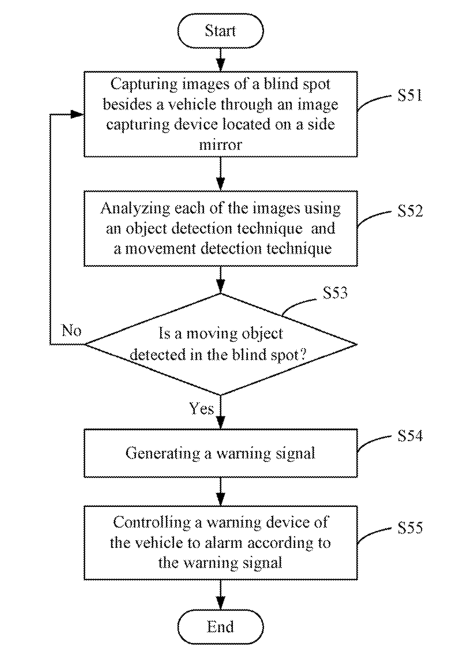
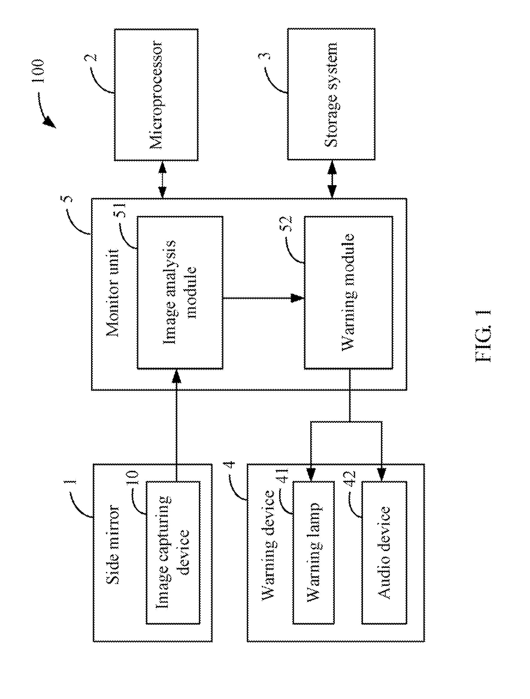
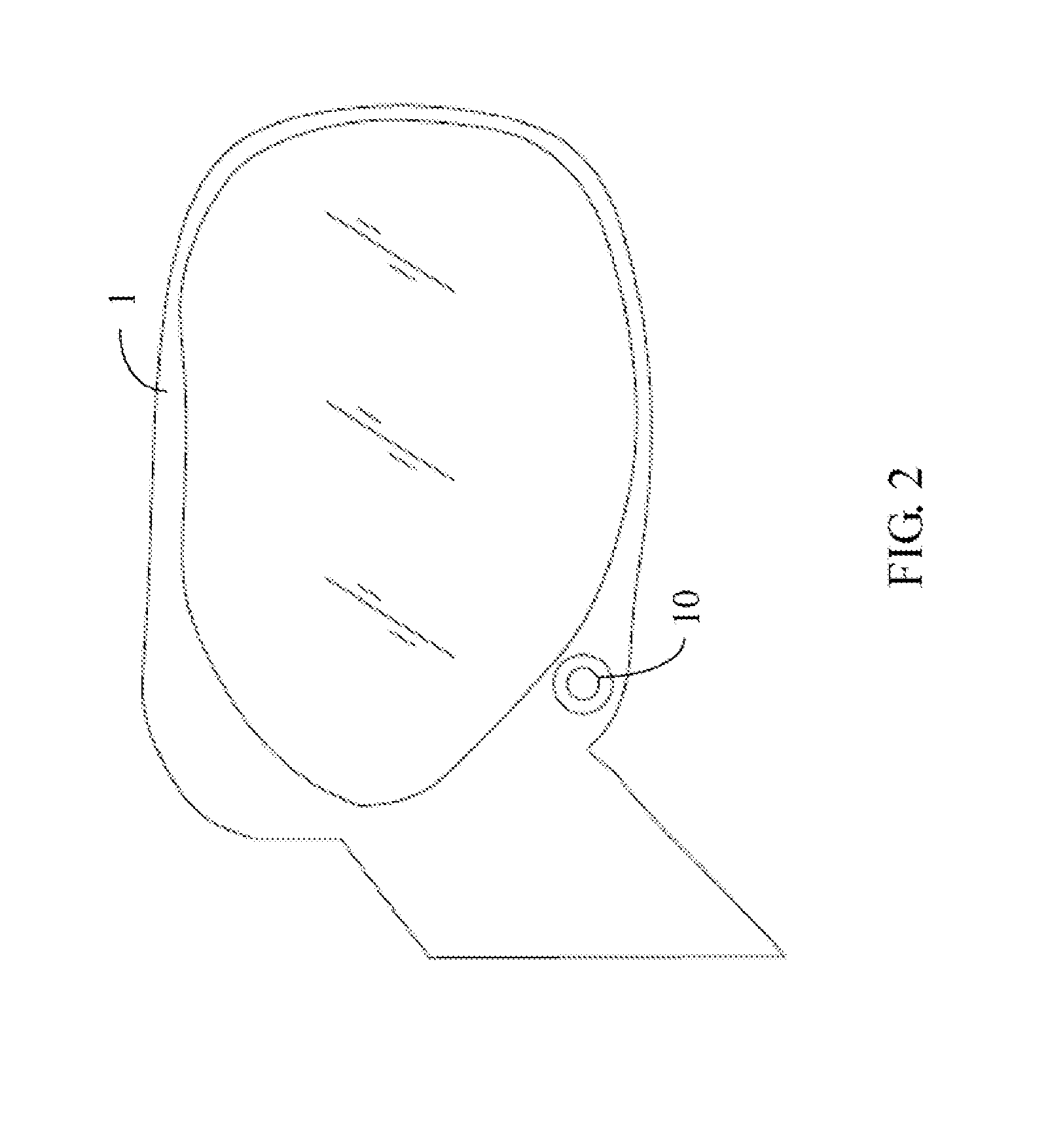
[0011]FIG. 1 is a schematic diagram of one embodiment of a system for monitoring blind spots (hereinafter “the monitor system 100”) of a vehicle. The monitor system 100 can be installed in the vehicle, such as a car, a truck, a bus, or any other ground vehicle. The monitor system 100 can detect the blind spots of the vehicle while the vehicle is driven. In one embodiment, the monitor system 100 includes an image capturing device 10 located on at least one side mirror 1 of the vehicle, a microprocessor 2, a storage system 3, a warning device 4, and a monitor unit 5. The components 1-5 may communicate with each other through electrical wires embedd...


PUM


Abstract

A system for detecting blind spots of a vehicle while the vehicle is been driven includes an image capturing device of at least one side mirror, a warning device and a microprocessor. The image capturing device to capture images of the blind spots of the vehicle. Each of the captured images are analyzed to detect whether a moving object exists in the blind spot. A warning signal is generated in response to a detection of the moving object in the blind spots, and causing the warning device to alarm according to the warning signal.

Description

BACKGROUND[0001]1. Technical Field[0002]Embodiments of the present disclosure relate generally to monitor systems and methods, and more particularly to a system and method for monitoring blind spots of a vehicle.[0003]2. Description of Related Art[0004]Blind spots are areas of a road that cannot be seen while looking forward or through either the side or side mirrors during driving a vehicle. Vehicles in the adjacent lanes of the road may fall into these blind spots, and a driver may be unable to see them using only the mirrors. Unfortunately, a traffic emergency may happen if the driver cannot see what is in the blind spots. Blind spots can be eliminated by reducing overlap between side and side mirrors, or be checked by turning driver's head briefly, or by adding another mirror with a larger field of view.BRIEF DESCRIPTION OF THE DRAWINGS[0005]FIG. 1 is a schematic diagram of one embodiment of a system for detecting blind spots of a vehicle.[0006]FIG. 2 is a schematic diagram illu...

Claims


Application Information

Patent Timeline
Patent Type & Authority Applications(United States)
IPC IPC(8): B60Q1/00H04N7/18
CPCB60Q9/008
Inventor LEE, HOU-HSIENLEE, CHANG-JUNGLO, CHIH-PING
Owner HON HAI PRECISION IND CO LTD
Why Eureka
Try Eureka