Liquid crystal display

a liquid crystal display and liquid crystal technology, applied in non-linear optics, instruments, optics, etc., can solve the problems of deterioration of response speed during voltage application, uneven orientation of liquid crystal molecules, and deterioration of effective aperture ratio, so as to avoid the increase of resistance value and disconnection of electrodes, avoid deterioration of display quality, and expand the distance between adjacent openings.

Active Publication Date: 2011-10-06
STANLEY ELECTRIC CO LTD
View PDF4 Cites 6 Cited by
  • Summary
  • Abstract
  • Description
  • Claims
  • Application Information

AI Technical Summary

Benefits of technology

[0010]According to the display of the above-described invention, the distance between adjacent openings can be considerably expanded in the first electrode and the second electrode, respectively. Consequently, it is possible to avoid the increase in resistance value and disconnection of the electrodes caused by the connection of the openings, and thereby avoid deterioration of the display quality.

Problems solved by technology

With a liquid crystal display provided with numerous rectangular openings described above, depending on the layout of the openings, the orientation of the liquid crystal molecules may become uneven, and there are cases where problems such as deterioration in the effective aperture ratio or deterioration in the response speed during voltage application may occur.
If this kind of connection of openings occurs frequently, it will incur a rise in the resistance value of the electrode, and there is concern that the display quality will deteriorate.
Moreover, if all openings adjacent in the longitudinal direction become connected, it will incur the disconnection of the electrode, and there is concern that a display defect will occur and that the display quality will deteriorate.

Method used


Image

  • Liquid crystal display
  • Liquid crystal display
  • Liquid crystal display

Examples


Embodiment Construction

[0032]Embodiments of the present invention are now explained with reference to the appended drawings.

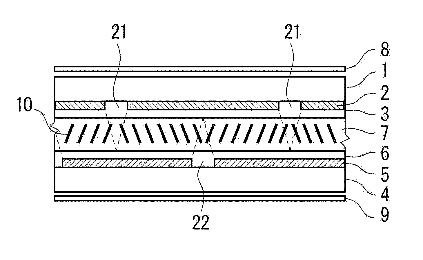
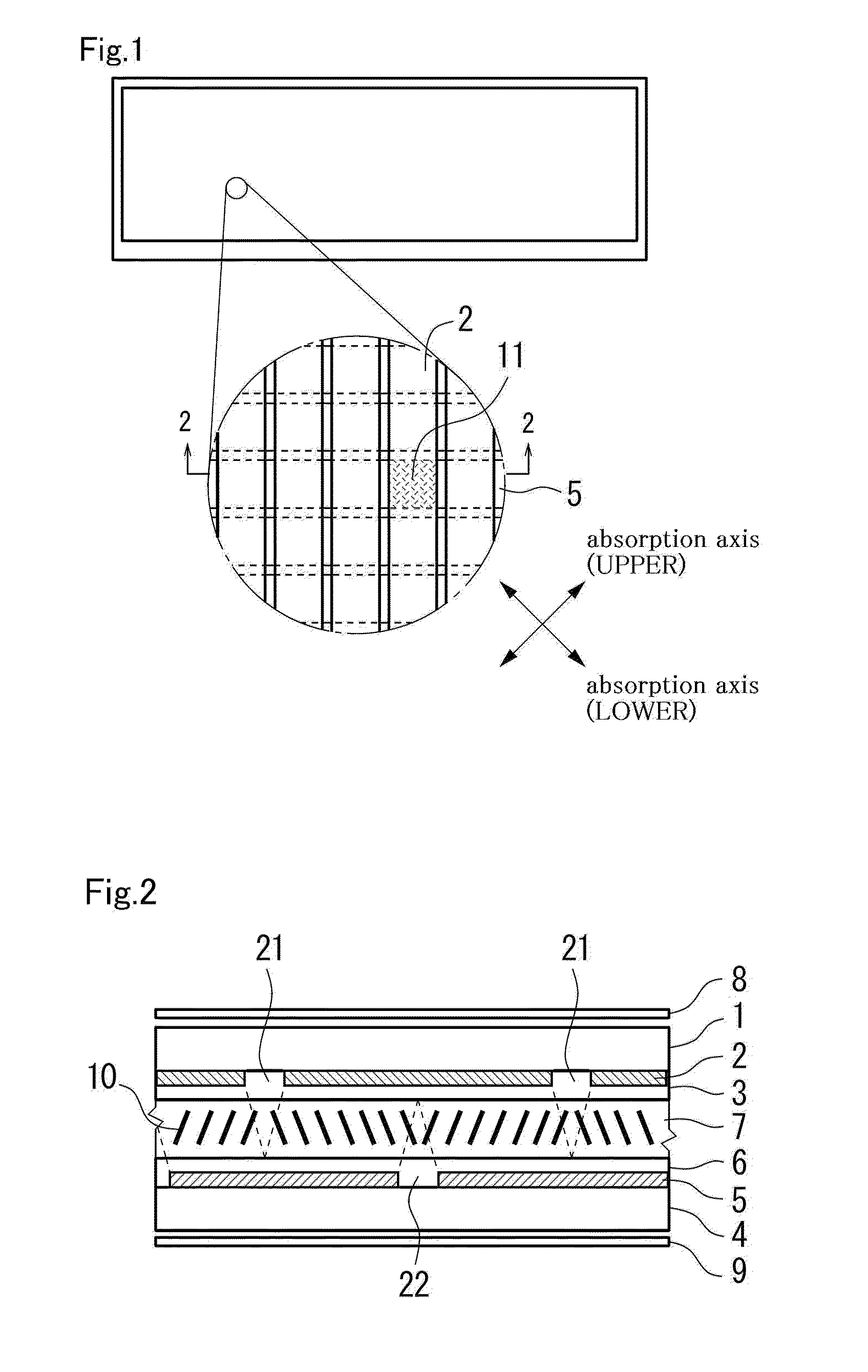
[0033]FIG. 1 shows a schematic external view and a partial enlarged view of the liquid crystal display according to one embodiment. Moreover, FIG. 2 is a partial cross section of line 2-2 of the liquid crystal display shown in FIG. 1. The liquid crystal display of this embodiment shown in the respective drawings is configured by including an upper substrate (first substrate) 1, a plurality of upper electrodes (first electrodes) 2, an oriented film 3, a lower substrate (second substrate) 4, a plurality of lower electrodes (second electrodes) 5, an oriented film 6, a liquid crystal layer 7, an upper polarizing plate (first polarizing plate) 8, and a lower polarizing plate (second polarizing plate) 9.

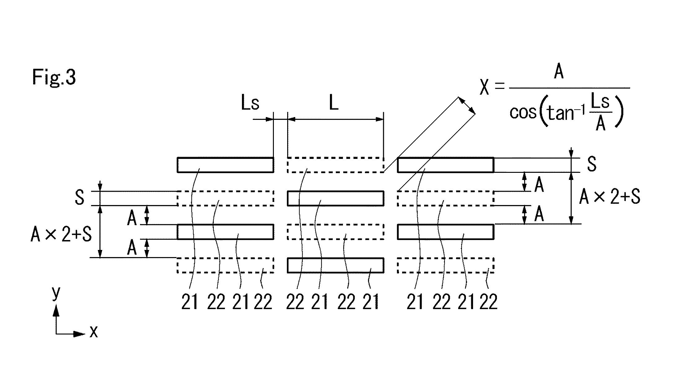
[0034]As shown in the partial enlarged view of FIG. 1, with the liquid crystal display of this embodiment, the respective overlapping locations (intersecting areas) of the upper electrode 2...


PUM

PropertyMeasurementUnit
widthsaaaaaaaaaa
mutual distanceaaaaaaaaaa

Abstract

The liquid crystal display comprises a first substrate having a first electrode formed on one side, and a second substrate having a second electrode formed on one side and which is placed opposite to the first substrate so that the second electrode and the first electrode of the first substrate face each other. A liquid crystal layer is provided between the first substrate and the second substrate. The first electrode includes a plurality of first openings provided in a regular checkered pattern with each first opening having a shape extending in a first direction. The second electrode includes a plurality of second openings provided in a regular checkered pattern with each second opening having a shape extending in the first direction. The plurality of first openings and the plurality of second openings are relatively arranged so that each of the plurality of first openings is positioned between two second openings which are adjacent in a planar view among the plurality of second openings.

Description

BACKGROUND OF THE INVENTION[0001]1. Field of the Invention[0002]The present invention relates to a liquid crystal display with a plurality of openings (slits) formed on an electrode.[0003]2. Description of the Background Art[0004]As an information display device, a display device with extremely low display brightness of the background display area or the dark display area is demanded, and a vertical alignment liquid crystal display is known as a display device capable of realizing the same. A vertical alignment liquid crystal display is able to achieve extremely low transmissivity in the initial oriented state since the optical characteristics during the front face observation in the initial oriented state are approximately equal to the optical characteristics in a polarizing plane of a crossed nicols arrangement.[0005]With the foregoing vertical alignment liquid crystal display, in order to obtain favorable viewing-angle characteristics even during voltage application, it is effect...

Claims


Application Information

Patent Timeline
Patent Type & Authority Applications(United States)
IPC IPC(8): G02F1/1333
CPCG02F1/133707G02F1/1393G02F1/134309G02F1/133753
Inventor IWAMOTO, YOSHIHISA
Owner STANLEY ELECTRIC CO LTD
Why Eureka
Try Eureka