Electro-optical apparatus, manufacturing method thereof, and electronic device

a manufacturing method and electronic device technology, applied in the direction of basic electric elements, electrical devices, electrical equipment, etc., can solve the problems of reducing the reflectivity of the reflective layer, increasing the number of processes, and affecting the performance of the reflective electrode, so as to prevent the reduction of the reflectivity of the reflective electrode and reduce the resistance value of the terminal

Active Publication Date: 2017-06-06
LUMITEK DISPLAY TECH LTD
View PDF11 Cites 5 Cited by
  • Summary
  • Abstract
  • Description
  • Claims
  • Application Information

AI Technical Summary

Benefits of technology

[0009]An advantage of some aspects of the invention is to provide an electro-optical apparatus which is able to reduce a resistance value of a terminal while preventing a reduction of reflectivity of the reflective electrode, a manufacturing method thereof, and an electronic device provided with such an electro-optical apparatus.

Problems solved by technology

In addition, there are times when electrolytic corrosion occurs between the reflective conductive material and the transparent conductive material.
As a countermeasure, manufacturing the terminals using another processes is considered, but manufacturing costs rise due to an increase in the number of processes.
However, in a case where the same material as the wiring layer is used in the reflective layer, there is a concern that reflectivity of the reflective layer is reduced.

Method used


Image

  • Electro-optical apparatus, manufacturing method thereof, and electronic device
  • Electro-optical apparatus, manufacturing method thereof, and electronic device
  • Electro-optical apparatus, manufacturing method thereof, and electronic device

Examples


modification example

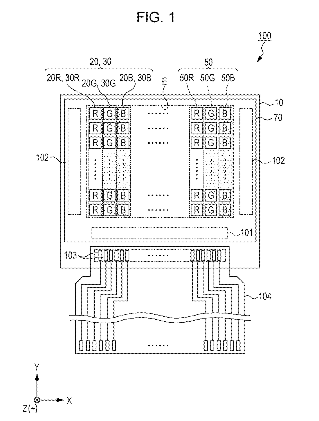
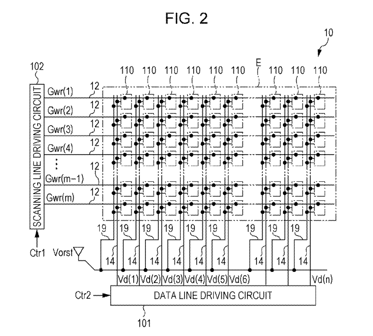
[0116]Next, an organic EL apparatus 200 which is illustrated in FIGS. 10 and 11 will be described as a modification example of the organic EL apparatus 100. Here, FIG. 10 is a planar view illustrating a configuration of the pixels 20 (pixels 20B, 20G, and 20R). FIG. 11 is a sectional view of the pixel 20G using the line segment XI-XI which is illustrated in FIG. 10. In addition, in the description below, the parts which are the same as the organic EL apparatus 100 described above will be omitted from the description and given the same reference numerals in the drawings.

[0117]As shown in FIGS. 10 and 11, the organic EL apparatus 200 is provided with a reflective electrode 60 which is configured by a portion of the power supply line 6 in place of the reflective electrode 35 which is disposed so as to be split into each pixel 20. That is, the reflective electrode 60 is disposed in common to each of the pixels 20B, 20G, and 20R.

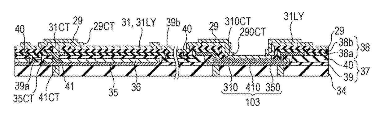
[0118]In addition, as shown in FIG. 3, in the power supply ...


PUM


Abstract

There is provided an electro-optical apparatus including an element substrate that includes a display region in which a plurality of light-emitting elements are arranged, and a peripheral region in which a terminal is disposed. The light-emitting element has a structure in which a reflective electrode, an optical adjustment layer, a first electrode, a light-emitting layer, and a second electrode are laminated, and the first electrode is electrically connected to a contact electrode. The terminal has a structure in which a first terminal layer that is formed by a first conductive film which is the same as the reflective electrode, a second terminal layer that is formed by a second conductive film which is the same as the contact electrode, and a third terminal layer that is formed by a third conductive film which is the same as the first electrode are laminated.

Description

BACKGROUND[0001]1. Technical Field[0002]The present invention relates to an electro-optical apparatus, a manufacturing method thereof, and an electronic device.[0003]2. Related Art[0004]An organic electro luminescence (EL) apparatus, in which pixels that use an organic EL element are disposed in a matrix form in a display region of an element substrate, is proposed as an example of the electro-optical apparatus (for example, refer to JP-A-2010-198754).[0005]In detail, JP-A-2010-198754 discloses a top emission structure organic EL apparatus that has an organic EL element in which a reflective layer, a first electrode (pixel electrode), a light-emitting layer, and a second electrode (counter electrode) are laminated in that order.[0006]Here, in the organic EL apparatus described in JP-A-2010-198754, a plurality of terminals, which include a mounting terminal for mounting a data line driving circuit, a scanning line driving circuit, and the like, an external connection terminal, and th...

Claims


Application Information

Patent Timeline
Patent Type & Authority Patents(United States)
IPC IPC(8): H01L51/52H01L27/32H01L51/00
CPCH01L51/5203H01L27/3276H01L27/3297H01L27/3262H01L51/0023H01L51/5253H01L51/5265H01L2227/323H10K59/131H10K50/856H10K71/00H10K59/124H10K59/1315H10K59/1213H10K71/621H10K50/852H10K2102/3026H10K59/1201H10K59/805H10K50/805H10K50/818H10K59/35H10K50/844H10K2102/00H10K2102/103
Inventor KOSHIHARA, TAKESHI
Owner LUMITEK DISPLAY TECH LTD
Why Eureka
Try Eureka