Wireless communication terminal apparatus, wireless communication base station apparatus and signal spreading method

a technology wireless communication terminal, which is applied in the field of wireless radio communication base station apparatus, and response signal spreading method, can solve the problems of severe interference from other cells, and achieve the effect of increasing the overhead of uplink control channel and comp communication

Active Publication Date: 2011-10-06
SUN PATENT TRUST
View PDF22 Cites 40 Cited by
  • Summary
  • Abstract
  • Description
  • Claims
  • Application Information

AI Technical Summary

Benefits of technology

[0031]According to the present invention, without increasing an overhead of uplink control channel, CoMP communication can be performed.

Problems solved by technology

However, because of influences such as a misalignment of transmitting timing at a terminal and a delayed wave caused by multipath, multiple response signals from multiple terminals may not arrive at to a base station at the same time.
This can randomize the combination of response signals to suffer severe interference from other cells, so that no longer do some terminals alone continue suffering severe interference from other cells.

Method used


Image

  • Wireless communication terminal apparatus, wireless communication base station apparatus and signal spreading method
  • Wireless communication terminal apparatus, wireless communication base station apparatus and signal spreading method
  • Wireless communication terminal apparatus, wireless communication base station apparatus and signal spreading method

Examples


embodiment 1

[0049]FIG. 9 shows a configuration of base station 100 according to the present embodiment, and FIG. 10 shows a configuration of terminal 200 according to the present embodiment.

[0050]Here, to avoid complicated explanation, FIG. 9 shows only components pertaining to a transmission of downlink data and a reception in an uplink of the response signal associated with the downlink data, to which the present invention is closely related, and illustration and description of parts or components pertaining to uplink data reception are omitted. In the same way, FIG. 10 shows only components pertaining to a reception of downlink data and a transmission in an uplink of the response signal associated with the downlink data, to which the present invention is closely related, and illustration and description of parts or components pertaining to uplink data reception are omitted.

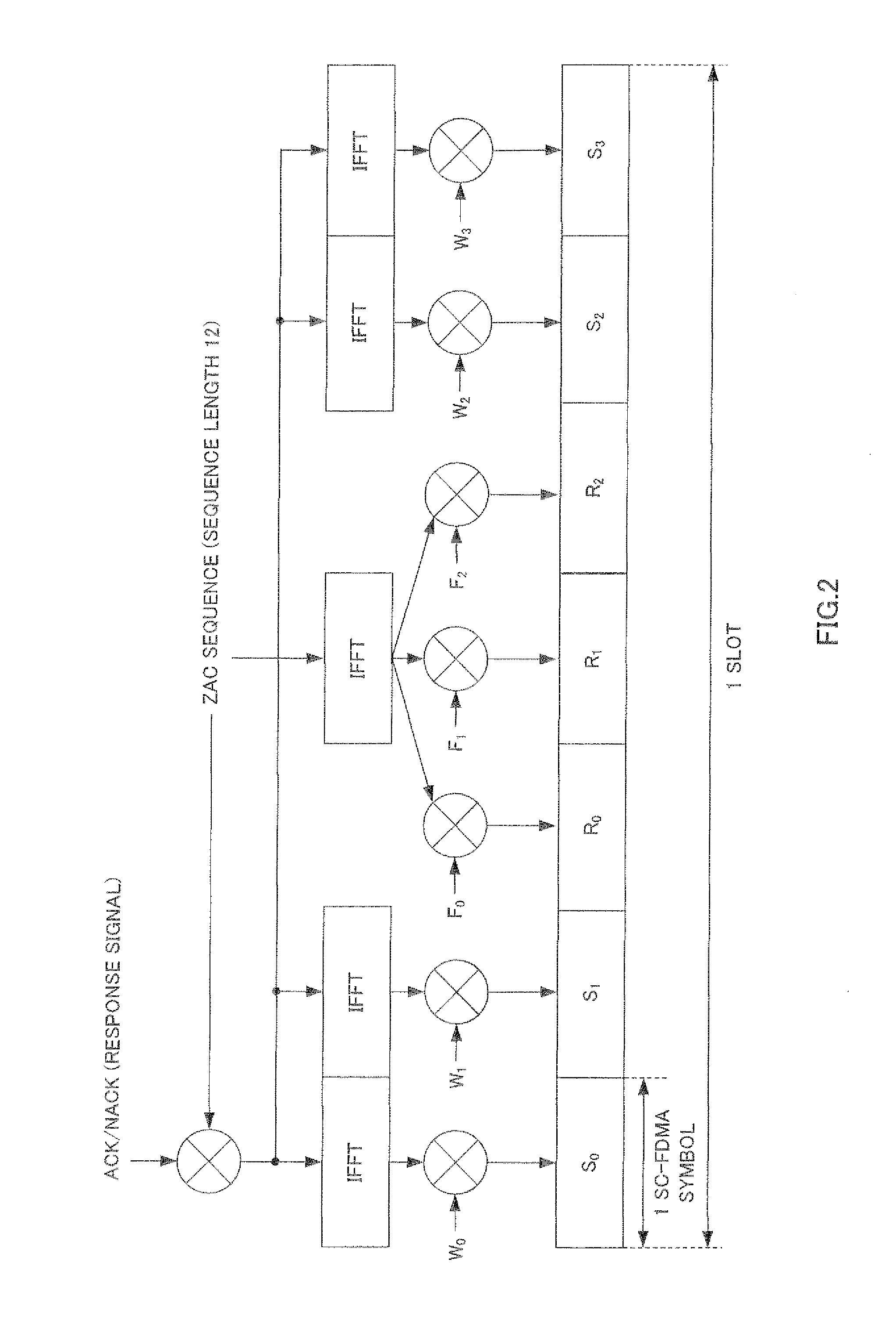
[0051]Then, in the following explanation, a case will be explained where a ZAC sequence is used for the first spreading ...

embodiment 2

[0110]A case has been described with embodiment 1 where multiple base stations receive response signals in CoMP reception. By contrast with this, a case will be described with the present embodiment where a plurality of base stations join the same CoMP group, transmit in CoMP transmission downlink data (a reference signal) to a terminal, and receive in CoMP reception a CQI signal shows the quality of a downlink measured using the downlink data (a reference signal).

[0111]The detail will be described in the following. In the following description, a plurality of base stations join the same CoMP group transmit a reference signal and downlink data in. CoMP transmission. Thus, reference signals from a plurality of base stations are code-multiplexed and received at a terminal. A base station reports to a terminal in advance information showing a resource (for example, PRB) to be used to transmit a CQI signal.

[0112]A configuration of base station 300 according to the present embodiment is ...

embodiment 3

[0126]Assuming that slot synchronization is established between multiple base stations joining the same CoMP group cases have been described with embodiment 1 and embodiment 2 where slot numbers match between all the base stations joining the same CoMP group. By contrast with this, a case where slot synchronization is not established between multiple base stations joining the same CoMP group—that is, a case where slot numbers do not match between all the base stations joining the same CoMP group—will be described with the present embodiment.

[0127]Here, a hopping pattern of a control signal (a response signal or a CQI signal) is defined by cyclic shifting for each slot a resource arrangement of a control channel (PUCCH) for a control signal on a cyclic shift axis. Then, a base station and a terminal according to the present embodiment adjust a hopping pattern showing correspondence between a resource arrangement and slot numbers of multiple control channels on a cyclic shift axis, us...


PUM


Abstract

A wireless communication terminal apparatus wherein CoMP communication can normally be performed without increasing the overhead of an upstream line control channel. In this apparatus, a spreading unit (214) primarily spreads a response signal by use of a ZAC sequence established by a control unit (209). A spreading unit (217) secondarily spreads the response signal, to which CP has been added, by use of a block-wise spread code sequence established by the control unit (209). The control unit (209) controls, in accordance with sequence numbers and a hopping pattern established therein, the circular shift amount of the ZAC sequence to be used for the primary spread in the spreading unit (214) and the block-wise spread code sequence to be used for the secondary spread in the spreading unit (217). The hopping pattern established in the control unit (209) is a hopping pattern common to a plurality of base stations that CoMP-receive the response signal.

Description

TECHNICAL FIELD[0001]The present invention relates to a radio communication terminal apparatus, radio communication base station apparatus, and response signal spreading method.BACKGROUND ART[0002]In 3GPP LTE, SC-TDMA (Single-Carrier Frequency Division Multiple Access) is employed as an uplink communication method (see Non-patent Literature 1). In 3GPP LTE, a radio communication base station apparatus (hereinafter simply referred to as “base station”) allocates resources for uplink data to a radio communication terminal apparatus (hereinafter simply referred to as “terminal”) through a physical channel (for example, PDCCH (Physical Downlink Control Channel)).[0003]Also, in 3GPP LTE, HARQ (Hybrid Automatic Repeat reQuest) is applied to downlink data from a base station to a terminal. Thus, a terminal feeds back to a base station a response signal showing an error detection result of downlink data. A terminal performs a CRC (Cyclic Redundancy Check) check for downlink data, feed backs...

Claims


Application Information

Patent Timeline
Patent Type & Authority Applications(United States)
IPC IPC(8): H04B1/713H04J13/00
CPCH04J11/0053H04B1/7143H04L1/0026H04L5/0032H04B7/024H04J13/22
Inventor NAKAO, SEIGOSUZUKI, HIDETOSHIIMAMURA, DAICHI
Owner SUN PATENT TRUST
Why Eureka
Try Eureka