User equipment, base station device, communication system, and handover control method

a technology for user equipment and communication systems, applied in the field of user equipment, base station devices, communication systems, and handover control methods, can solve problems such as the inability to handover

Active Publication Date: 2011-10-06
PANASONIC INTELLECTUAL PROPERTY CORP OF AMERICA
View PDF3 Cites 34 Cited by
  • Summary
  • Abstract
  • Description
  • Claims
  • Application Information

AI Technical Summary

Problems solved by technology

At the time when the UE is handed over from an eNB to an HeNB, however, the handover cannot be accomplished only by detecting an HeNB of good reception quality, and it is still necessary to perform a process of checking the presence of access permission for the HeNB of handover destination.
When the same frequency is used, there may be a problem of interference between a signal from a UE connected to the CSG cell and that from another UE connected to a macro cell.

Method used


Image

  • User equipment, base station device, communication system, and handover control method
  • User equipment, base station device, communication system, and handover control method
  • User equipment, base station device, communication system, and handover control method

Examples


first embodiment

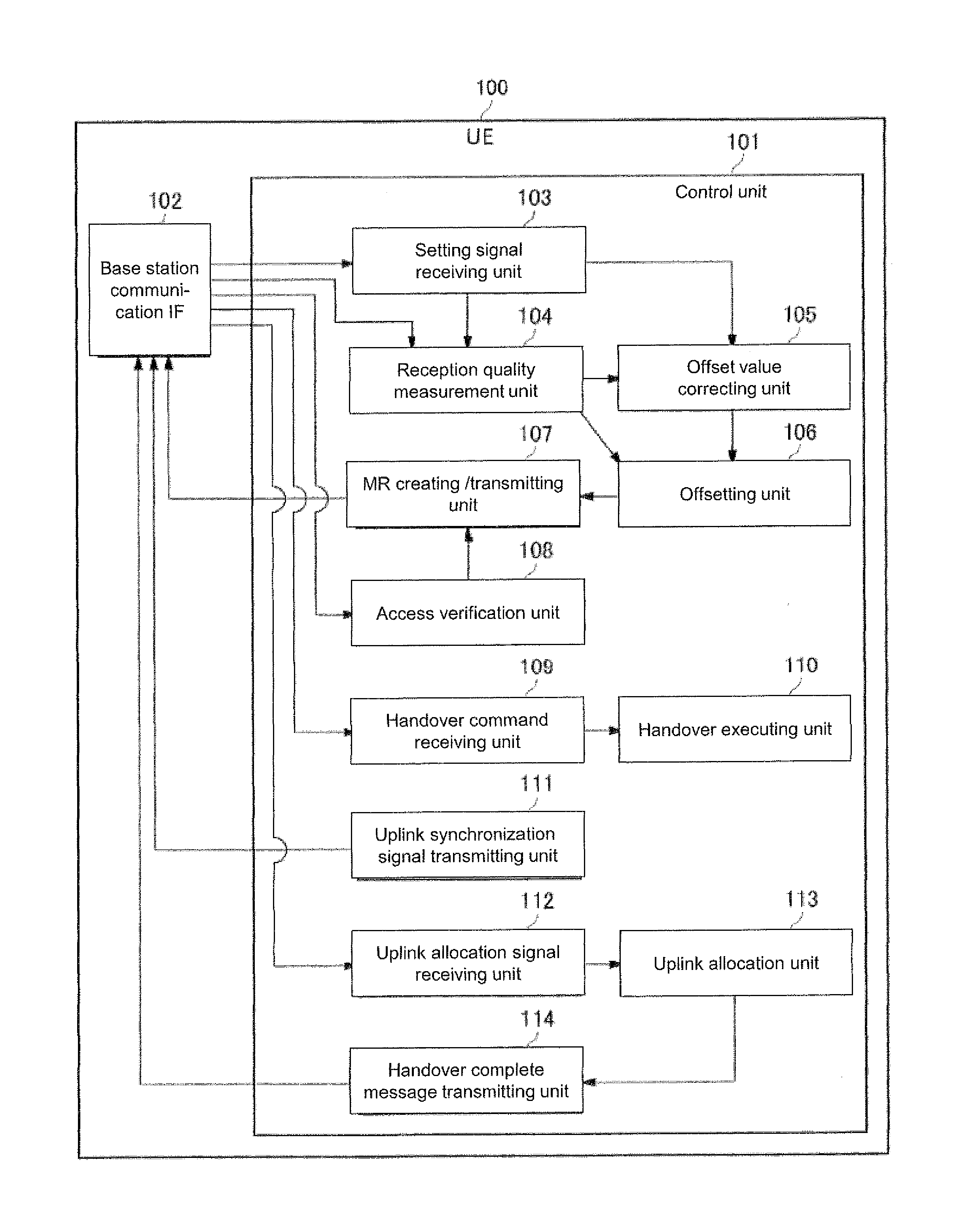
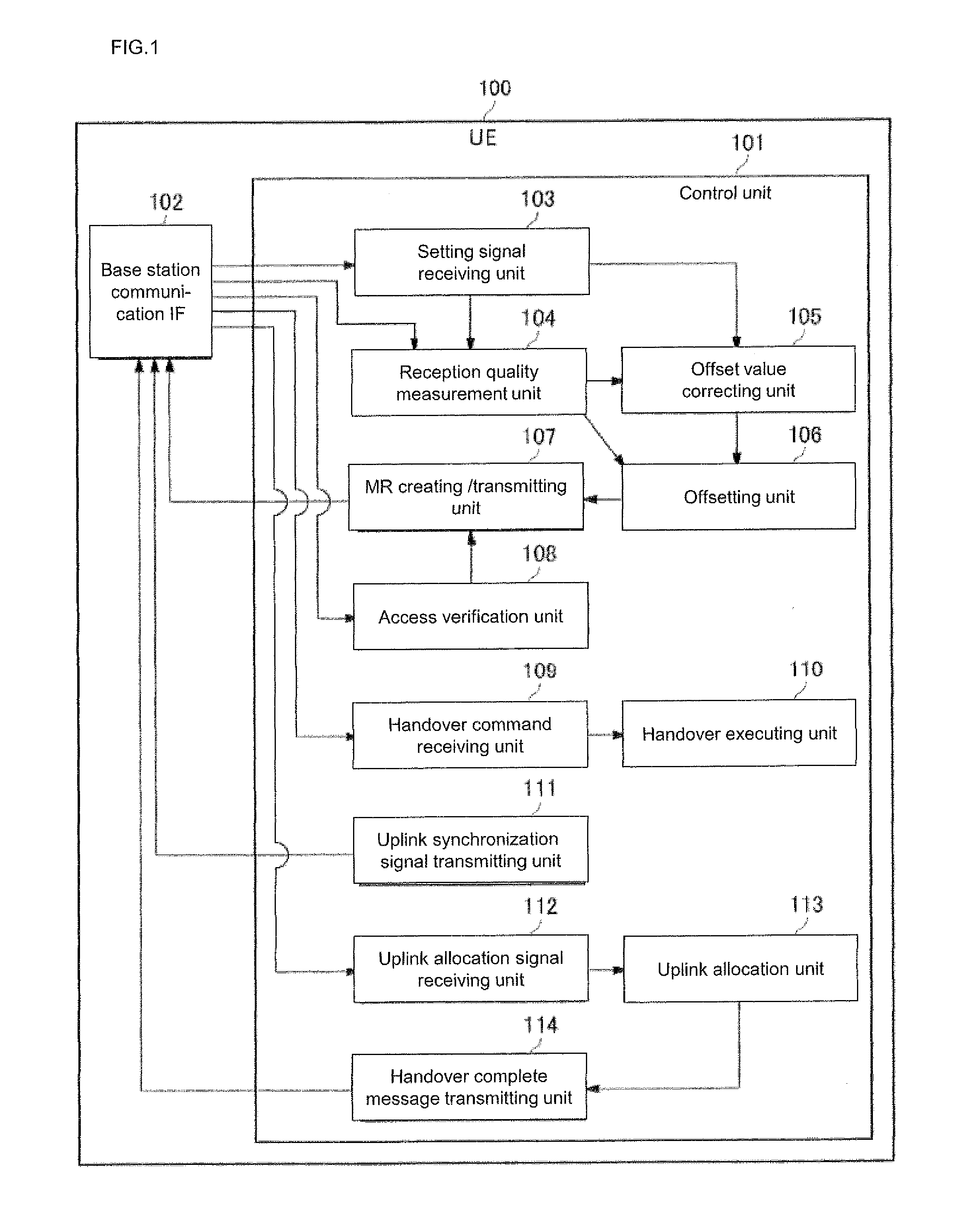
[0066]A communication system according to a first embodiment of the present invention will now be described below with reference to FIGS. 1 to 7. First, description will be made to a configuration of a UE according to the embodiment. FIG. 1 is a block diagram for illustrating a configuration of a UE according to the embodiment. As shown in FIG. 1, a UE 100 comprises a control unit 101 responsible for a handover-related control, and a base station communication IF 102 that is an interface (IF) for communicating with a base station (such as an eNB 200 and an HeNB 300).

[0067]The control unit 101 of the UE 100 comprises a setting signal receiving unit 103 for receiving a setting (measurement control) signal for reception quality measurement transmitted by the eNB 200, and a reception quality measurement unit 104 for measuring reception quality of signals from the base station (such as the eNB 200 and the HeNB 300).

[0068]The control unit 101 of the UE 100 also comprises an offset value c...

second embodiment

[0102]A communication system according to a second embodiment of the present invention will now be described below with reference to FIGS. 8 to 10. Here, description will primarily be made to differences of the embodiment from the first embodiment. The configuration and operation of the second embodiment are similar to those of the first embodiment unless otherwise noted.

[0103]This embodiment is configured to notify correction values α and β and a threshold value by means of a broadcasting signal transmitted from the eNB 200, which is different from the first embodiment in which the correction values α and β and the threshold value are notified by means of a measurement control signal transmitted from the eNB 200 separately to the UE 100.

[0104]FIG. 8 is a block diagram for illustrating a configuration of the UE 100 according to the embodiment. As shown in FIG. 8, in addition to the configuration of the first embodiment, the UE 100 according to the embodiment has a broadcasting signa...

third embodiment

[0110]A communication system according to a third embodiment of the present invention will now be described below with reference to FIGS. 11 to 13. Here, description will primarily be made to differences of the embodiment from the first embodiment. The configuration and operation of the third embodiment are similar to those of the first embodiment unless otherwise noted.

[0111]This embodiment is configured to notify correction values α and β and a threshold value by means of a broadcasting signal transmitted from each HeNB 300, which is different from the first embodiment in which the correction values α and β and a threshold value are notified by means of a measurement control signal transmitted from the eNB 200 separately to the UE 100.

[0112]FIG. 11 is a block diagram for illustrating a configuration of the UE 100 according to the embodiment. As shown in FIG. 11, in addition to the configuration of the first embodiment, the UE 100 according to the embodiment has a broadcasting sign...


PUM


Abstract

In a user equipment (UE)(100), a handover from a macro cell base station (eNB)(200) to a CSG cell base station (HeNB)(300) is controlled based on a result of comparison between reception quality from the eNB (200) and reception quality from the HeNB (300) located in a macro cell. The UE (100) comprises: a reception quality measurement unit (104) for measuring the reception quality of the eNB (200) and the reception quality of the HeNB (300); an offsetting unit (106) for offsetting the reception quality of the HeNB (300) with an offset value that makes the reception quality of the HeNB (300) relatively higher than the reception quality of the eNB (200); and an offset value correcting unit (105) for correcting the offset value according to the reception quality of the eNB (200). A user equipment is thereby provided in which handover control can be performed with an appropriate offset value that takes into consideration interference in the uplink from the user equipment to the base station.

Description

TECHNICAL FIELD[0001]The present invention relates to a user equipment in which a handover is controlled based on reception quality of a signal from a base station.BACKGROUND ART[0002]Recently, one idea under consideration in 3GPP is that providing a home base station (HeNB) for use indoors in a cell formed by a regular base station (eNB), or a macro cell, to form a CSG cell. The HeNB has a function of regulating user equipment (UE) that may be allowed to access the HeNB, and the UE can only access an HeNB for which the UE has access permission. Accordingly, even when the UE detects an HeNB, the UE cannot connect to the HeNB without access permission no matter how good reception quality the HeNB has.[0003]To obtain access permission, the UE must examine a cell identification (cell ID) included in system information transmitted from the HeNB. Cell IDs include a physical cell ID (PCI) that locally identifies an eNB, a cell global ID (CGI) that uniquely identifies every eNB, and the li...

Claims


Application Information

Patent Timeline
Patent Type & Authority Applications(United States)
IPC IPC(8): H04W36/00
CPCH04W36/04H04W84/045H04W36/30
Inventor MATSUO, HIDENORIAOYAMA, TAKAHISA
Owner PANASONIC INTELLECTUAL PROPERTY CORP OF AMERICA
Why Eureka
Try Eureka