Illuminating safety and notification device

a safety and notification device technology, applied in the field of safety lighting devices, can solve the problems of flares releasing noxious fumes, user burns, and inability to carry a portable ligh

Active Publication Date: 2011-10-13
STAMATATOS HARALAMBOS A +1
View PDF4 Cites 66 Cited by
  • Summary
  • Abstract
  • Description
  • Claims
  • Application Information

AI Technical Summary

Benefits of technology

[0006]The safety beacon of the present invention includes an arrangement of light emitting diodes (LEDs) controlled by a controller circuit and powered by a rechargeable battery source. The rechargeable battery source will recharge when coupled to any appropriate power source, including a power outlet within a vehicle and a conventional wall power outlet. Further, when coupled to such a power source, the safety beacon will draw power for operation from the power source without using the battery source. The safety beacon encases the LEDs with a base of a hard rubber casing and an outer housing forming a lens made of a high impact clear plastic. The safety beacon includes a port and connecting cable so that multiple safety beacons can be strung together. In such a configuration, the multiple safety beacons are configured to share power with all safety beacons within the chain. In some embodiments, the safety beacon includes a magnet within its base for affixing the safety beacon to metal surfaces, such as the surface of an automobile. The safety beacon also is operated either manually or by a remote control device.
[0007]In an aspect of the present invention, a portable lighting device comprises one or more light emitting diodes, a power source coupled to the light emitting diodes, a controller coupled to the light emitting diodes and to the power source to control operation of the portable lighting device and a connection port configured to couple the portable lighting device to a second portable lighting device. In some embodiments, the power source is rechargeable. The portable lighting device further comprises a power port, wherein the power source is recharged by connecting a connector cable to the power port and to a power outlet. Alternatively, the power source is a battery. In a further alternate embodiment, the power source is a solar cell. The portable lighting device further comprises a base for supporting the light emitting diodes. The portable lighting device further comprises a protective housing for protecting the light emitting diodes. The protective housing forms a lens for the light emitting diodes. The portable lighting device further comprises a wireless receiver coupled to the controller for receiving control signals from one or more of a remote control device and the second portable lighting device. Ub some embodiments, the wireless receiver receives radio frequency signals from the remote control device. The wireless receiver alternatively receives infrared signals from the remote control device. Power and control signals are shared between the portable lighting device and the second portable lighting device. The portable lighting device further comprises an attachment means for affixing the portable lighting device to a surface. In some embodiments, the attachment means is a magnet. The portable lighting device further comprises a supporting base adapter configured to couple to a safety cone and provide a support platform for supporting the portable lighting device.
[0008]In another aspect, a safety device comprises a light source, a power source coupled to the light source, a controller coupled to the light source and the power source to control operation of the lighting device, and a connection port that transmits and receives power up and control signals. In some embodiments, the connection port transmits and receives a wired signal. In further embodiments, the connection port transmits and receives a wireless signal. In some embodiments, the connection port receives a signal from an external source. In some of these embodiments, the external source is a remote control. In further embodiments, the external source is a program located on a computing device. In still further embodiments, the external source is one or more additional connection port of one or more additional safety devices. In some embodiments, the signal is a signal to power the light source. In some embodiments, the safety device further comprises an attachment mechanism for attaching the safety device to an additional object. In some embodiments, th

Problems solved by technology

When the flare is ignited there is a risk of burning to the user.
Also, when burning, the flare releases noxious fumes.
However, in certain instances it is not practical to carry

Method used


Image

  • Illuminating safety and notification device
  • Illuminating safety and notification device
  • Illuminating safety and notification device

Examples


Embodiment Construction

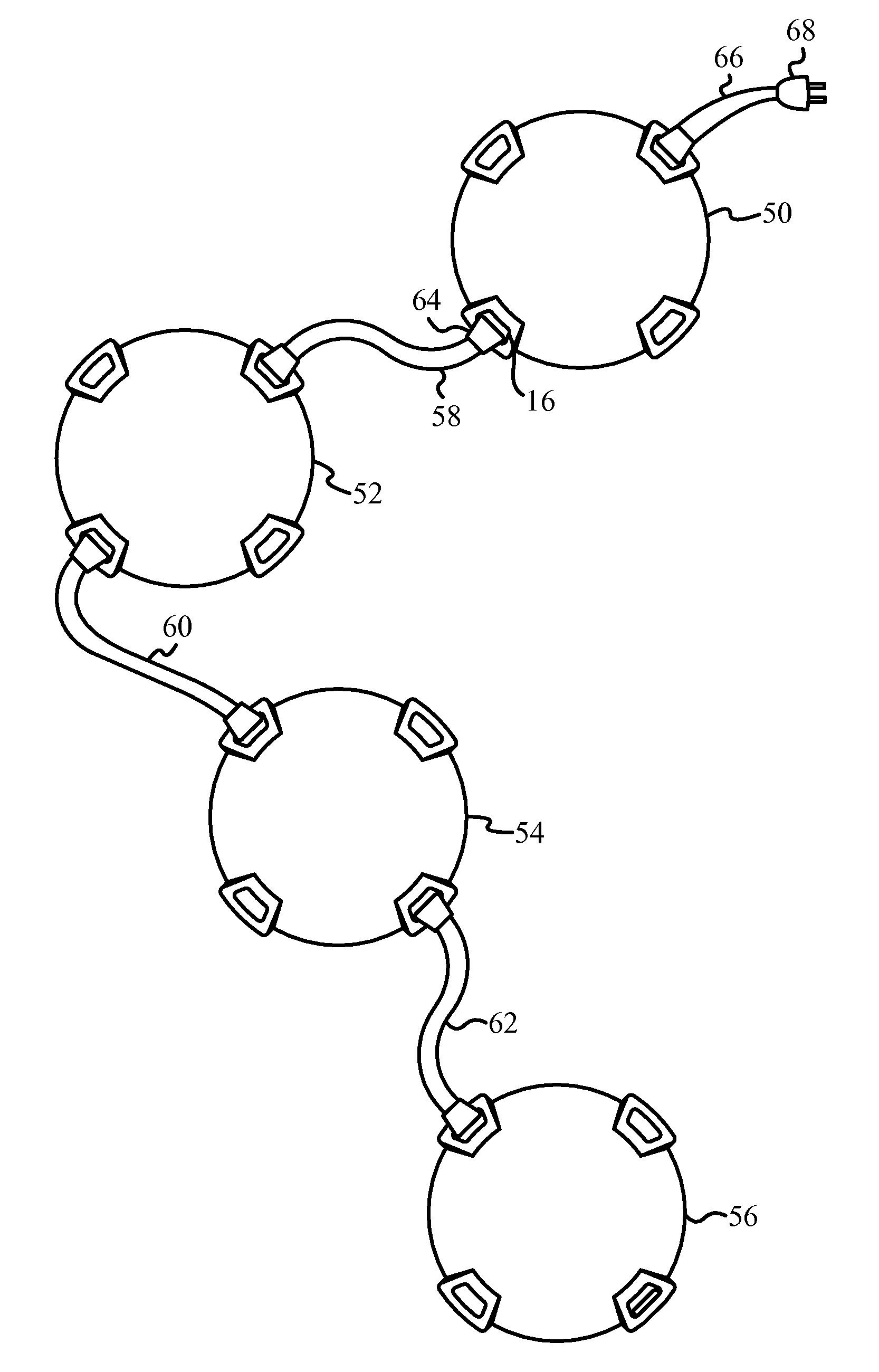
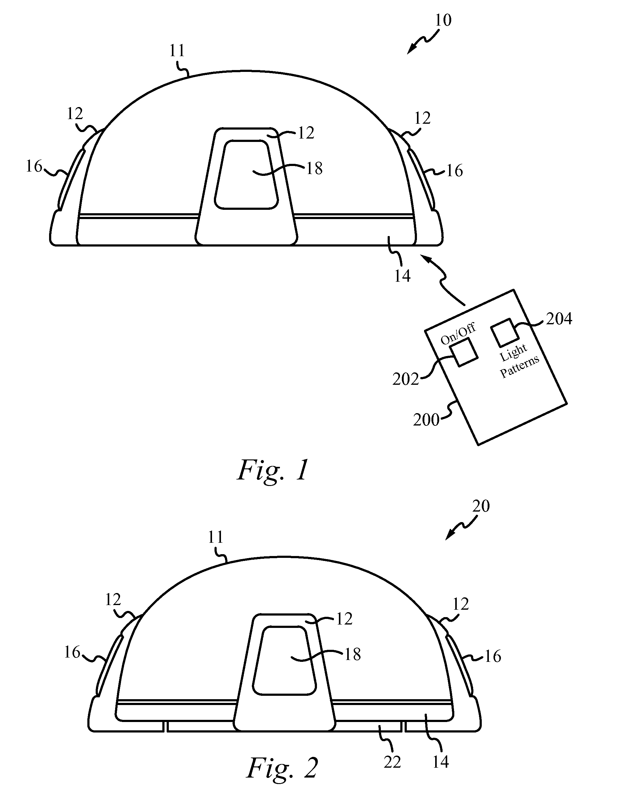
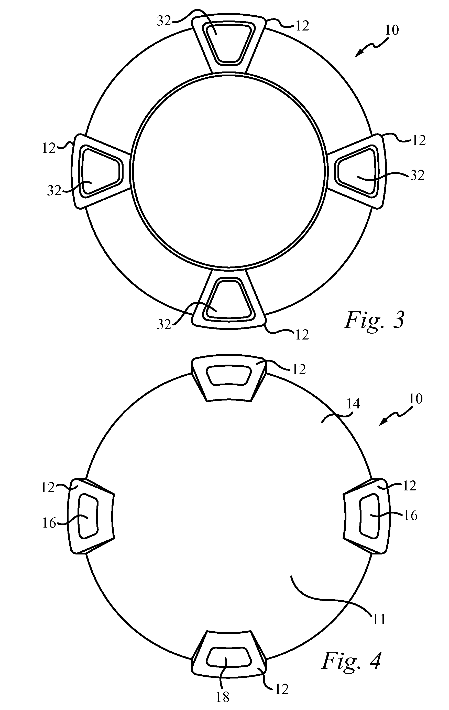
[0031]The safety beacon of the present invention is an identification light source or safety light with multiple uses. The safety beacon includes an arrangement of light emitting diodes (LEDs) controlled by a controller circuit. In some embodiments, the LEDs and the controller circuit are powered by a rechargeable battery source. The rechargeable battery source will recharge when coupled to any appropriate power source, including a power outlet within a vehicle and a conventional wall outlet. Further, when coupled to such a power source, the safety beacon will draw power for operation from the power source without using the battery source. The safety beacon encases the array of LEDs with a base of a hard rubber casing and an outer housing forming a lens and made of a high impact clear plastic. The safety beacon includes a port and connecting cable so that multiple safety beacons can be strung together. In such a configuration, the multiple safety beacons are configured to share powe...


PUM


Abstract

A safety device comprises a light source, a power source coupled to the light source, a controller coupled to the light source and the power source to control operation of the lighting device, and a connection port that transmits and receives power up and control signals. In some embodiments, the connection port transmits and receives a wired signal. In further embodiments, the connection port transmits and receives a wireless signal. In some embodiments, the connection port receives a signal from an external source. In some of these embodiments, the external source is a remote control. In further embodiments, the external source is a program located on a computing device. In still further embodiments, the external source is one or more additional connection port of one or more additional safety devices. In some embodiments, the signal is a signal to power the light source.

Description

RELATED APPLICATIONS[0001]This patent application is a continuation-in-part of the U.S. patent application Ser. No. 10 / 423,271, filed Apr. 25, 2003, and entitled “ILLUMINATING SAFETY AND NOTIFICATION DEVICE,” which claims priority under 35 U.S.C. §119(e) of the U.S. provisional application Ser. No. 60 / 376,140 filed on Apr. 25, 2002 and entitled “ILLUMINATING SAFETY AND NOTIFICATION DEVICE.” The U.S. patent application Ser. No. 10 / 423,271, filed Apr. 25, 2003, and entitled “ILLUMINATING SAFETY AND NOTIFICATION DEVICE,” and the provisional application Ser. No. 60 / 376,140 filed on Apr. 25, 2002 and entitled “ILLUMINATING SAFETY AND NOTIFICATION DEVICE” are both hereby incorporated by reference.FIELD OF THE INVENTION[0002]The present invention relates to lighting devices. More particularly, the present invention relates to safety lighting devices for providing a warning or alert to persons within the vicinity of the lighting device.BACKGROUND OF THE INVENTION[0003]Traditionally, roadsid...

Claims


Application Information

Patent Timeline
IPC IPC(8): F21L4/02H05B37/02F21L4/00
CPCB60Q1/2615F21Y2101/02B60Q7/00B60Q2900/30E01F9/065F21S8/032F21S8/033F21S9/03F21V21/0885F21V21/096F21V23/0435F21V23/0442F21W2111/00F21W2111/02B60Q1/52E01F9/559F21Y2115/10F21W2131/10Y02B20/72
Inventor STAMATATOS, HARALAMBOS A.O'BOYLE, BRIAN
Owner STAMATATOS HARALAMBOS A
Why Eureka
Try Eureka