Systems and methods for enhanced imaging of objects within an image

a technology of enhanced imaging and objects, applied in image enhancement, instruments, applications, etc., can solve the problems of affecting the quality of image enhancement, difficult, sometimes impossible, and inability to provide adequate visualization of instruments inserted at a steep angle with respect to the ultrasound transducer used to generate, etc., to achieve the effect of avoiding image clutter and reducing the number of images

Active Publication Date: 2011-10-13
FUJIFILM SONOSITE
View PDF11 Cites 56 Cited by
  • Summary
  • Abstract
  • Description
  • Claims
  • Application Information

AI Technical Summary

Benefits of technology

[0015]Other embodiments of the invention operate to identify an area or block of interest within a frame for combining or blending with one or more other frames to form a final image. For example, a block in which an interventional instrument is to be disposed may be known or determined. Thus, embodiments of the invention may crop, or ot

Problems solved by technology

As a result, the visualization of individual objects is typically compromised to achieve an overall satisfactory ultrasound image quality.
Thus, it is not a simple task to provide high quality visualization of one or more individual objects within an overall high quality ultrasound image.
Using ultrasound imaging systems configured with imaging parameters selected to optimize overall image quality, it is often difficult, and sometimes impossible, to provide adequate visualization of instruments inserted at a steep angle with respect to an ultrasound transducer used to generate an ultrasound image.
The problem of poor visualization of instruments inserted at steep angles results, at least in part, from the fact that representations of such instruments in ultrasound images are based on ultrasound echoes that are reflected from the instruments in a specular fashion.
The principles of specular reflection indicate that for steep insertion angles the ultrasou

Method used


Image

  • Systems and methods for enhanced imaging of objects within an image
  • Systems and methods for enhanced imaging of objects within an image
  • Systems and methods for enhanced imaging of objects within an image

Examples


Embodiment Construction

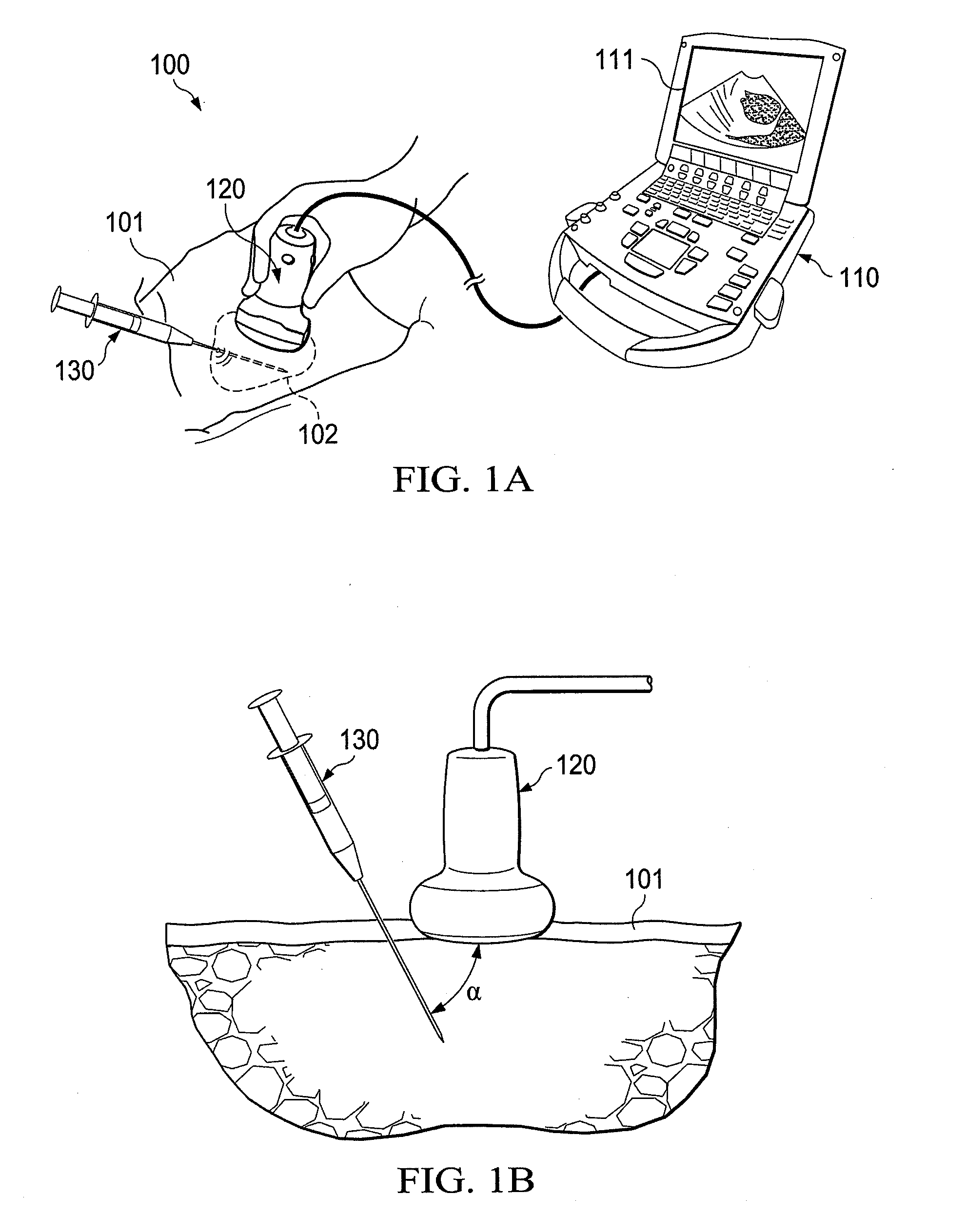
[0028]FIG. 1A shows an ultrasound imaging system adapted according to an embodiment of the invention. Specifically, ultrasound imaging system 100 is shown comprising system unit 110 coupled to transducer 120. System unit 110 of embodiments comprises a processor-based system operable to control transducer 120 to transmit and receive ultrasound signals, to process the received ultrasound signals, to generate an image using the processed received ultrasound signals, and to display the generated image (e.g., on display 111). Transducer 120 comprises an array of ultrasound elements operable to controllably transmit and receive ultrasound signals. Detail with respect to imaging systems which may be adapted according to the concepts of the present invention is provided in co-pending and commonly assigned U.S. patent application Ser. No. 12 / 467,899 entitled “Modular Apparatus for Diagnostic Ultrasound,” the disclosure of which is hereby incorporated herein by reference.

[0029]In operation, u...


PUM


Abstract

Systems and methods which implement a plurality of different imaging signatures in generating an image frame are shown. A first imaging signature may be configured for providing relatively high quality images with respect to subsurface regions of living tissue, for example, whereas a second imaging signature may be configured for providing relatively high quality images with respect to interventional instruments inserted into living tissue at a steep angle. Image sub-frames generated using each such different imaging signature are blended to form a frame of the final image providing a relatively high quality image of various objects within the volume being imaged.

Description

REFERENCE TO RELATED APPLICATIONS[0001]The present application claims priority to co-pending U.S. Provisional Patent Application Ser. No. 61 / 321,666, entitled “Systems and Methods for Enhanced Imaging of Objects Within An Image”, filed Apr. 7, 2010, and is related to co-pending and commonly assigned U.S. patent application Ser. No. 11 / 749,319 entitled “System and Method for Optimized Spatio-Temporal Sampling,” filed May 16, 2007, and Ser. No. 11 / 854,371 entitled “System and Method for Spatial Compounding Using Phased Arrays,” filed Sep. 12, 2007, the disclosures of which are hereby incorporated herein by reference.TECHNICAL FIELD[0002]The invention relates generally to ultrasound imaging and, more particularly, to enhancing the visualization of objects within an image.BACKGROUND OF THE INVENTION[0003]Ultrasound imaging systems have gained wide acceptance for use in providing images of objects and areas which are not otherwise visible to an observer. Such ultrasound imaging systems a...

Claims


Application Information

Patent Timeline
IPC IPC(8): G06K9/00
CPCA61B8/0841G01S15/8995A61B19/5244G06T2207/10132G06T2207/20221G06T5/50A61B34/20A61B8/13A61B8/5246
Inventor PAGOULATOS, NIKOLAOSMA, QINGLINLUNDBERG, ANDREW K.HIPPE, RICHARDSIEDENBURG, CLINTON T.
Owner FUJIFILM SONOSITE
Why Eureka
Try Eureka