Taggant keying system for dispensing systems

a keying system and keying technology, applied in the field of dispensing systems, can solve the problems of affecting the quality of products in the dispenser, the dispensing system may also pose contamination and health concerns, and the manufacturer and distributor may lose the ability to control the quality of the product in the dispenser, so as to prevent the use of unauthorized refill units and prevent the dispensing

Inactive Publication Date: 2011-10-20
GOJO IND INC
View PDF43 Cites 40 Cited by
  • Summary
  • Abstract
  • Description
  • Claims
  • Application Information

AI Technical Summary

Problems solved by technology

Dispensers may directly hold a quantity of product, but such dispensers have been found to be both messy and difficult to service.
These bulk fill systems may also pose contamination and health concerns.
Although mechanical keys are helpful in ensuring that the proper refill unit is installed into the proper dispenser and that high quality product remains in the dispensers, these keying systems also have a number of disadvantages.
Thus, inferior fluid may be installed into a particular dispenser and the manufacturer and distributor may lose the ability to control quality of the product in the dispenser.
Mechanical keying also necessitates significant tooling costs underwritten by the manufacturer to design special nozzles and dispensers that are compatible with one another.
Accordingly, the inventory costs for maintaining refill units with a particular key is significant.
In addition, the lead time for manufacturing such a refill unit may be quite lengthy.
Moreover, the identification of a particular keying device in a dispenser may be lost or damaged so that it is difficult to determine which type of keying configuration is needed for the refill units.
Although effective in its stated purpose, the device disclosed in the patent suffers from the disadvantage that a specific orientation is required for installation of the refill unit.
It is believed that this design is lacking because it provides no teaching for adaptability for use with multiple dispensers.
It is also believed that the disclosed configuration is subject to a mis-alignment of the coils which may lead to mis-identification of the bag.
In addition, the use of a single coil as the emitting and receiving coils may lead to mis-identification of the bag.
This dispensing system, however, suffers from the disadvantage that it is not easily recycled.
Given the increasing desire to provide eco-friendly products and reduce the consumption of natural resources, the copper coils provided in this dispensing system may present a disadvantage.

Method used


Image

  • Taggant keying system for dispensing systems
  • Taggant keying system for dispensing systems
  • Taggant keying system for dispensing systems

Examples


Embodiment Construction

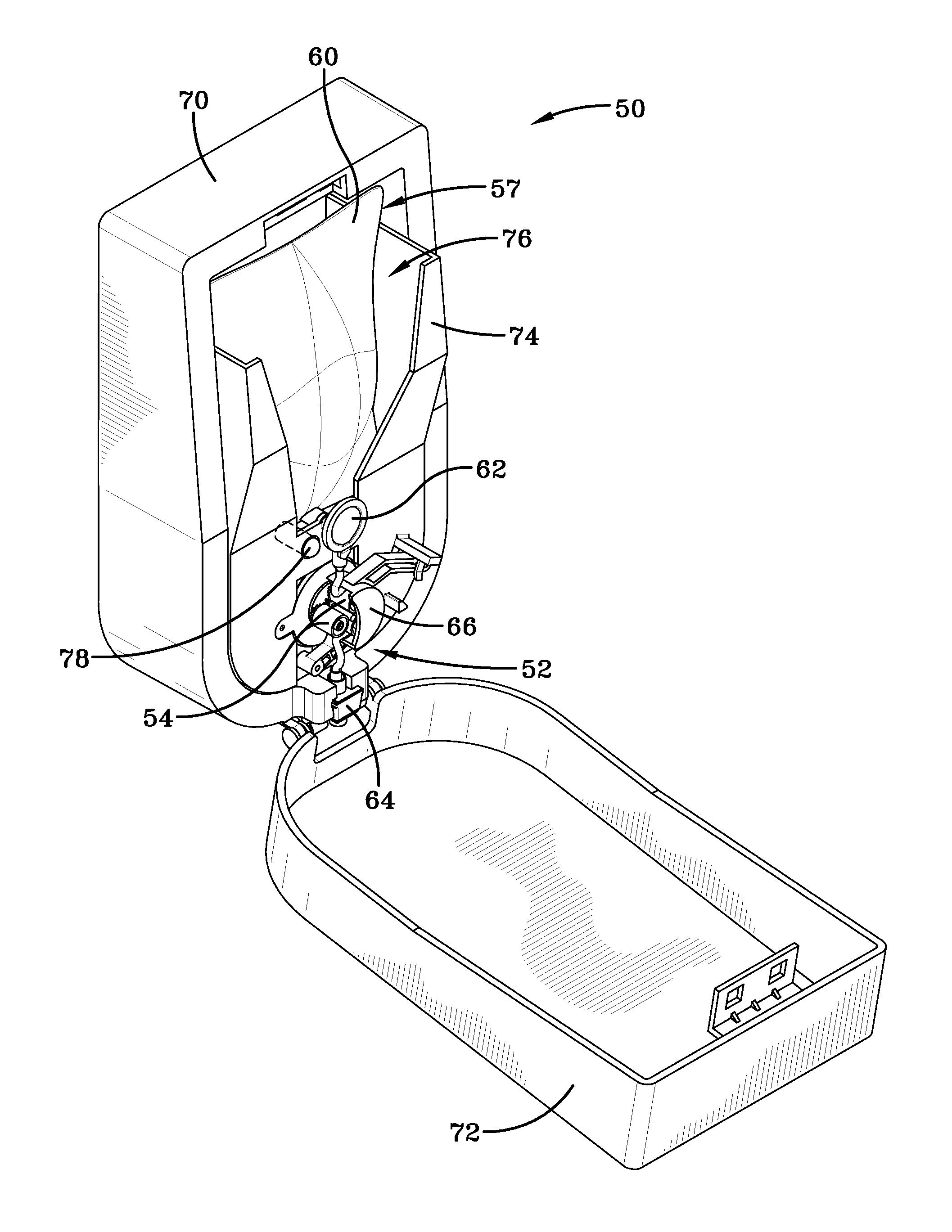
[0027]It will be appreciated from reading the background of the invention that a primary concern in the field of fluid dispensing systems is the ability to prevent unauthorized refill units from being installed in a manufacturer's dispenser or in dispensers serviced by a distributor authorized by the manufacturer. The dispensing system disclosed herein fills this need by providing the refill unit with a unique identifier, and providing the dispenser housing with a sensor adapted to sense the presence of only that unique identifier.

[0028]A microprocessor based controller is associated with either the refill unit, or the dispenser housing. The controller may be used to control any number of operational mechanisms that permit use of the dispensing system. The dispenser disclosed herein may utilize operational mechanisms such as a push bar mechanism or a “hands-free” automatic sensor mechanism for dispensing a quantity of product. The push bar mechanism may be actuated by pushing a bar ...


PUM


Abstract

A dispensing system with an electronic keying mechanism, the dispenser including a housing and a refill unit. The refill unit includes a product reservoir, a pump mechanism and a collar adapted to secure the refill unit within the housing. An infrared sensor is provided in the housing and includes an infrared radiation source and a detector. A taggant is dispersed within at least a portion of the collar, the taggant being detectable by the detector when exposed to infrared radiation.

Description

[0001]This application claims priority from U.S. Provisional Application Ser. No. 61 / 324,975 filed on Apr. 16, 2010, which is incorporated herein by reference in its entirety.FIELD OF THE INVENTION[0002]The present invention is generally directed to dispensing systems. In particular, the present invention is directed to keyed dispensers that allow only designated refill units to be installed therein. More specifically, the present invention is directed to electronically keyed fluid dispensing systems including an infrared radiation readable taggant dispersed within at least a portion of the refill unit.BACKGROUND OF THE INVENTION[0003]It is well known to provide fluid dispensers for use in restaurants, factories, hospitals, bathrooms and the home. These dispensers may contain one of a number of products such as, for example, soap, anti-bacterial cleansers, disinfectants, lotions and the like. The dispensers may include some type of pump actuation mechanism where the user pushes or p...

Claims


Application Information

Patent Timeline
Patent Type & Authority Applications(United States)
IPC IPC(8): B67D7/06
CPCA47K5/1217G07C9/00896A47K2005/1218A47K5/14A47K5/12G07C9/00
Inventor PELFREY, KEITH A.
Owner GOJO IND INC
Why Eureka
Try Eureka