
Medium suction support device and medium conveying device

a medium-sized suction hole and support device technology, which is applied in the direction of machine supports, other domestic objects, manufacturing tools, etc., can solve the problems of air leakage, air leakage, air leakage readily occurring, etc., and achieve the effect of reliably holding and satisfying the conveying

Active Publication Date: 2011-10-20
SEIKO EPSON CORP
View PDF23 Cites 6 Cited by
  • Summary
  • Abstract
  • Description
  • Claims
  • Application Information

AI Technical Summary

Benefits of technology

[0017]According to the first aspect, suction through the suction holes can be performed when the flexible tube members connected to the suction holes in the back surface of the medium support table are accommodated in the openings of the sliding member. When the sliding member moves in parallel to the medium support table, the other end sides of the flexible tube members separate from the openings of the sliding member and move up onto the sliding member, and the other opening ends are closed off by the sliding member. Air leakage from the suction holes is thereby minimized. Therefore, the recording medium can be reliably held by suction.
[0021]Air leakage when the suction holes are closed can thereby be minimized over a long period of time.
[0023]According to this aspect, suction through the suction holes can be performed when the other end sides of the flexible tube members disposed on the sliding member are in contact with areas that do not have suction holes in the back surface of the medium support table. When the sliding member moves in parallel with the medium support table, the other end sides of the flexible tube members surround the suction holes in the back surface of the medium support table. The opening ends of the flexible tube members are thereby fixed to and closed off by the sliding member, and air leakage from the suction holes is thereby minimized. Therefore, the recording medium can be reliably held by suction.
[0025]According to the present invention, satisfactory conveying can be achieved because the recording medium can be reliably held by suction on the medium support table.

Problems solved by technology

In other words, since there are open suction holes not covered by the recording medium, air will leak out from these suction holes (air leakage occurs).
However, a problem with the invention described above is that air leakage readily occurs, particularly when the invention is applied to a large printer.
This is because the platen and the shutter member in a large printer have large surface areas, and it is therefore not necessarily easy to tightly press the two together.
Another problem with the invention described above is that the cost of the device readily increases because a cam mechanism and sensors are used.

Method used


Image

  • Medium suction support device and medium conveying device
  • Medium suction support device and medium conveying device
  • Medium suction support device and medium conveying device

Examples


Embodiment Construction

[0035]Embodiments of the present invention are described hereinbelow with reference to the drawings.

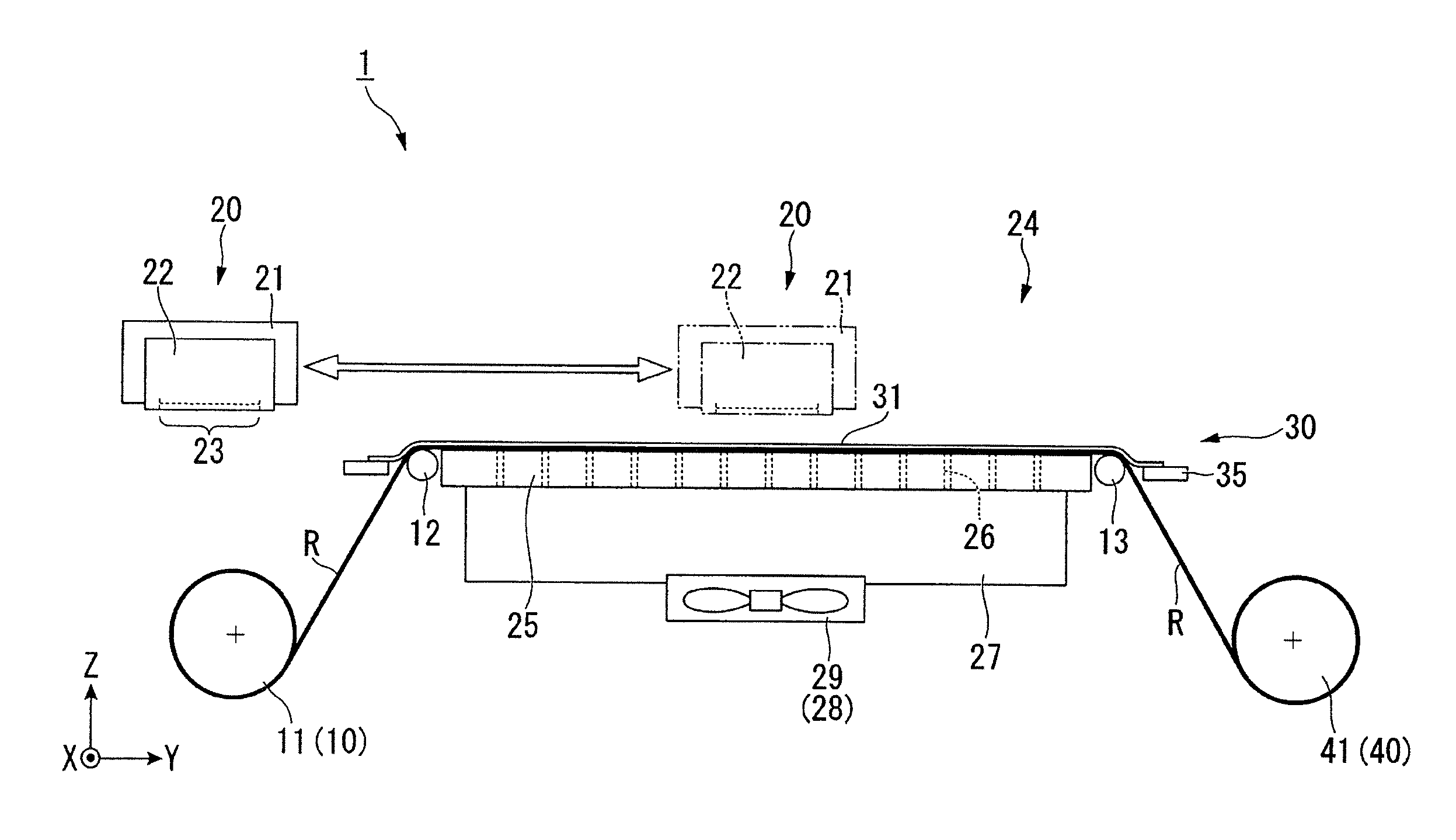
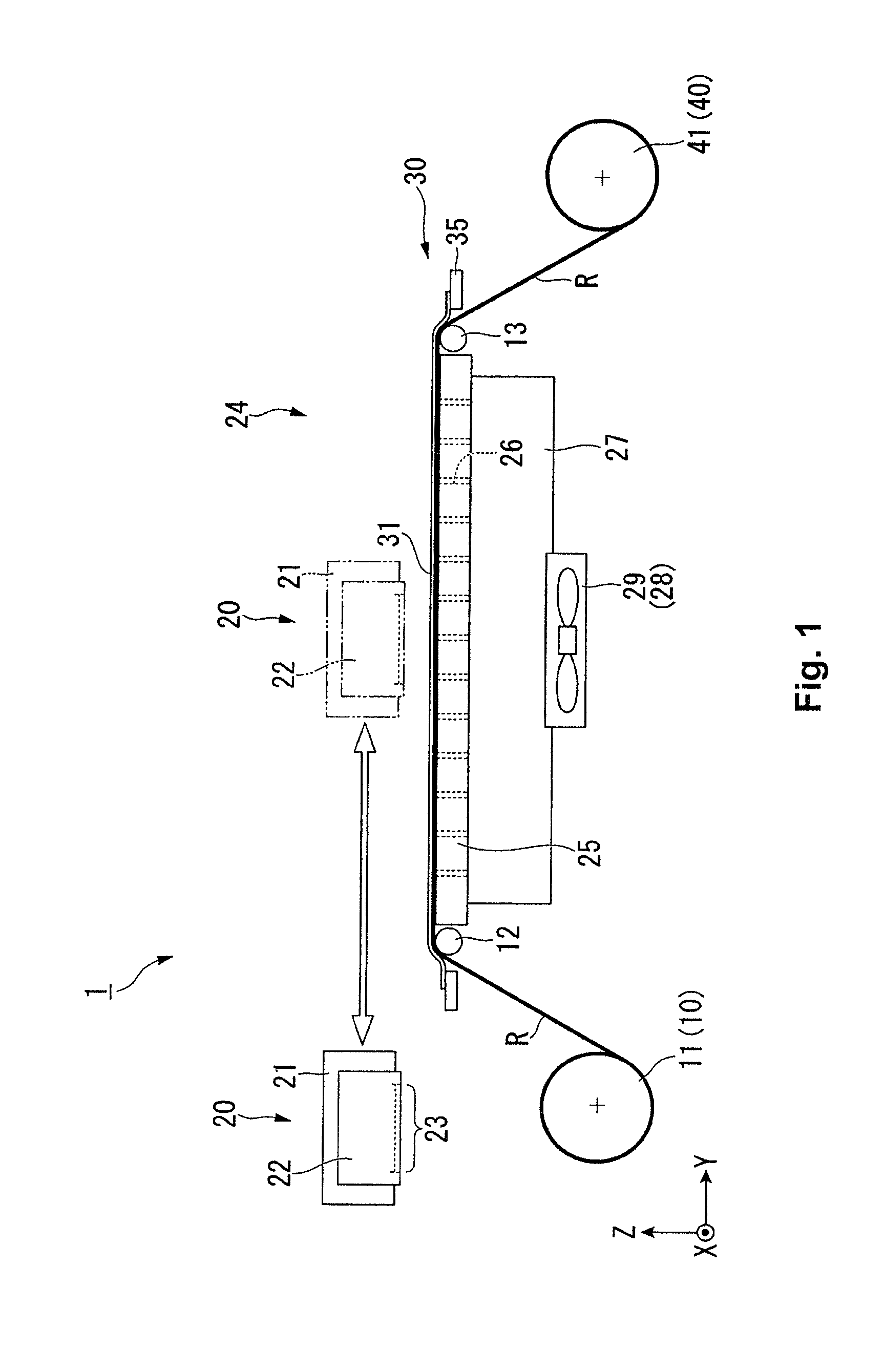
[0036]FIG. 1 is a side view showing the schematic configuration of an inkjet printer 1 according to the present embodiment.

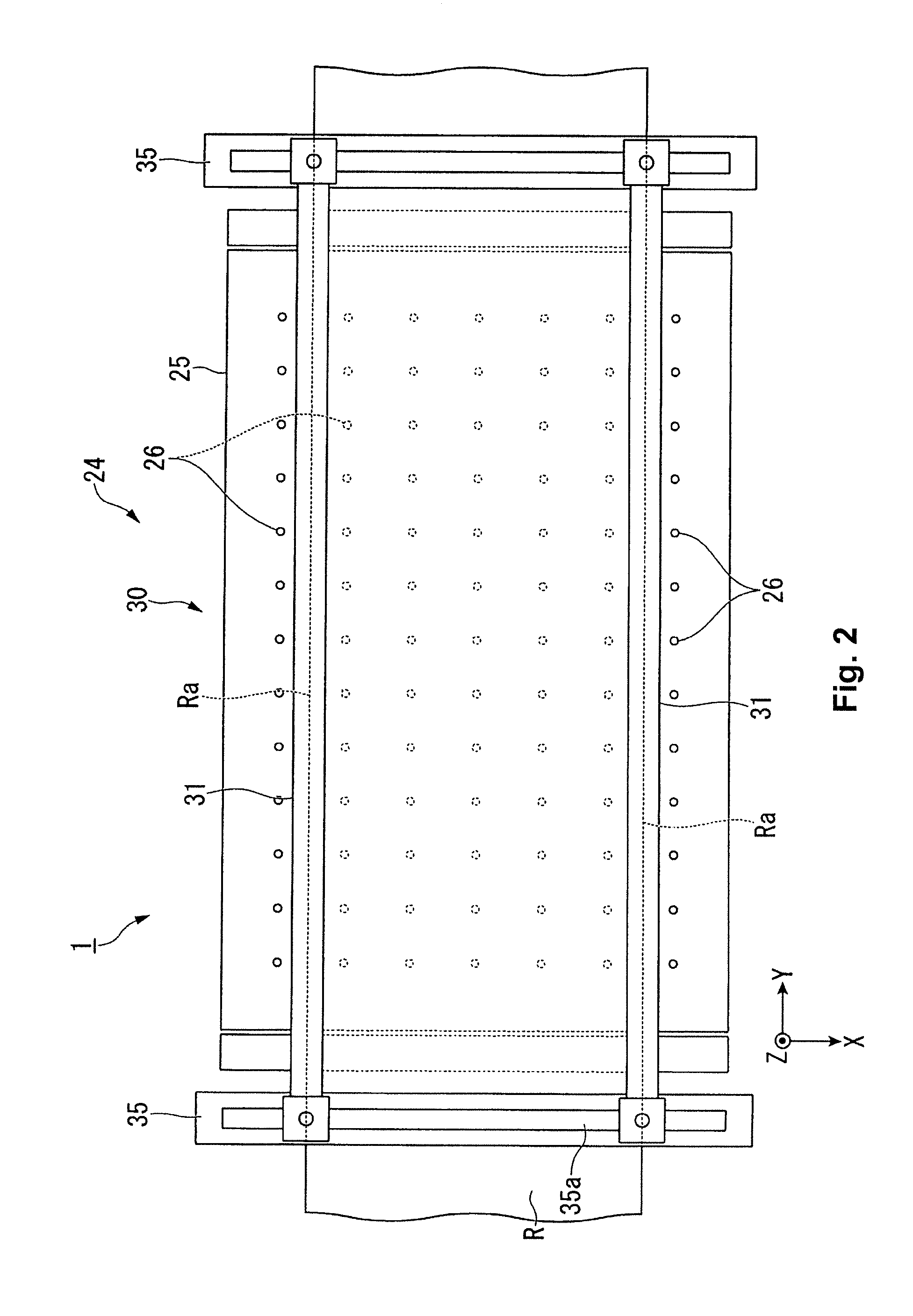
[0037]FIG. 2 is a top view showing the schematic configuration of the inkjet printer 1.

[0038]The inkjet printer 1 (the medium conveying device) comprises a feeding unit 10, a recording unit 20, and an ejection unit 40, as shown in FIG. 1.

[0039]The feeding unit (medium conveying unit) 10 is provided so as to be capable of feeding roll paper R, one example of a recording medium (supported medium), to the recording unit 20. Specifically, the feeding unit 10 has a roll medium holder 11, and the roll medium holder 11 holds the roll-shaped roll paper R in place. The configuration is designed so that by rotating the roll-shaped roll paper R, roll paper R unwound from the rolled state can be fed via a first roller 12 to the recording unit 20 downstream in the conveying di...


PUM


Abstract

A medium suction support device includes a medium support table, a suction unit, a plurality of flexible tube members and a sliding member. Through-holes are formed in the medium support table to pass through the medium support table. The suction unit is disposed on a side of the back surface to suction the recording medium disposed on the medium support surface via the through-holes. One opening end of each of the flexible tube members surrounds a corresponding one of the through-holes on the back surface. The sliding member is configured to move in parallel along the back surface. The sliding member has openings formed in an opposing surface facing the back surface with each of the openings being configured to respectively accommodate the other opening end of a corresponding one of the flexible tube members. The openings have different lengths in a parallel movement direction of the sliding member.

Description

CROSS-REFERENCE TO RELATED APPLICATIONS[0001]This application claims priority to Japanese Patent Application No. 2010-092934 filed on Apr. 14, 2010. The entire disclosure of Japanese Patent Application No. 2010-092934 is hereby incorporated herein by reference.BACKGROUND[0002]1. Technical Field[0003]The present invention relates to a medium suction support device for supporting a recording medium by suction, and a medium conveying device comprising the medium suction support device.[0004]2. Related Art[0005]In inkjet printers and other recording devices, when a recording process is performed on recording paper or another recording medium, the recording medium must be supported on a platen so as to have a certain alignment (a parallel alignment) relative to the recording head.[0006]Particularly when roll paper is used as the recording medium, the end of the roll paper rises up off the platen due to curling, and a paper suction part is therefore provided for suctioning the roll paper ...

Claims


Application Information

Patent Timeline
IPC IPC(8): B25B11/00B65H20/00
CPCB25B11/005B41J11/06B41J11/0085
Inventor TOYA, AKIHIRO
Owner SEIKO EPSON CORP
Learn More