Light emitting diode drive circuit device

Inactive Publication Date: 2011-10-20
ARTEAST TECH CORP
View PDF6 Cites 6 Cited by
  • Summary
  • Abstract
  • Description
  • Claims
  • Application Information

AI Technical Summary

Benefits of technology

[0007]The primary object of the present invention is to provide an LED drive circuit device, wherein the LEDs are installed in a lamp-set and two ends of the lamp-set are provided respectively with two pins to receive a high frequency AC (Alternating Current) outputted from ballasts, with the two pins being electrically connected with a drive circuit module. The drive circuit module includes primarily a resonant network correction circuit and a rectifying circuit, wherein using the resonant network correction circuit, the high frequency AC received from the two pins can be adjusted to comply with an application range of LED current, and then using the rectifying circuit, the AC i

Problems solved by technology

However, for this ignition method and the fitted lamp tube, scintillation of optical wave propagation will be produced when igniting.
Besides, the conventional ballast requires more electric energy, hence consumes more elect

Method used


Image

  • Light emitting diode drive circuit device
  • Light emitting diode drive circuit device
  • Light emitting diode drive circuit device

Examples


Example

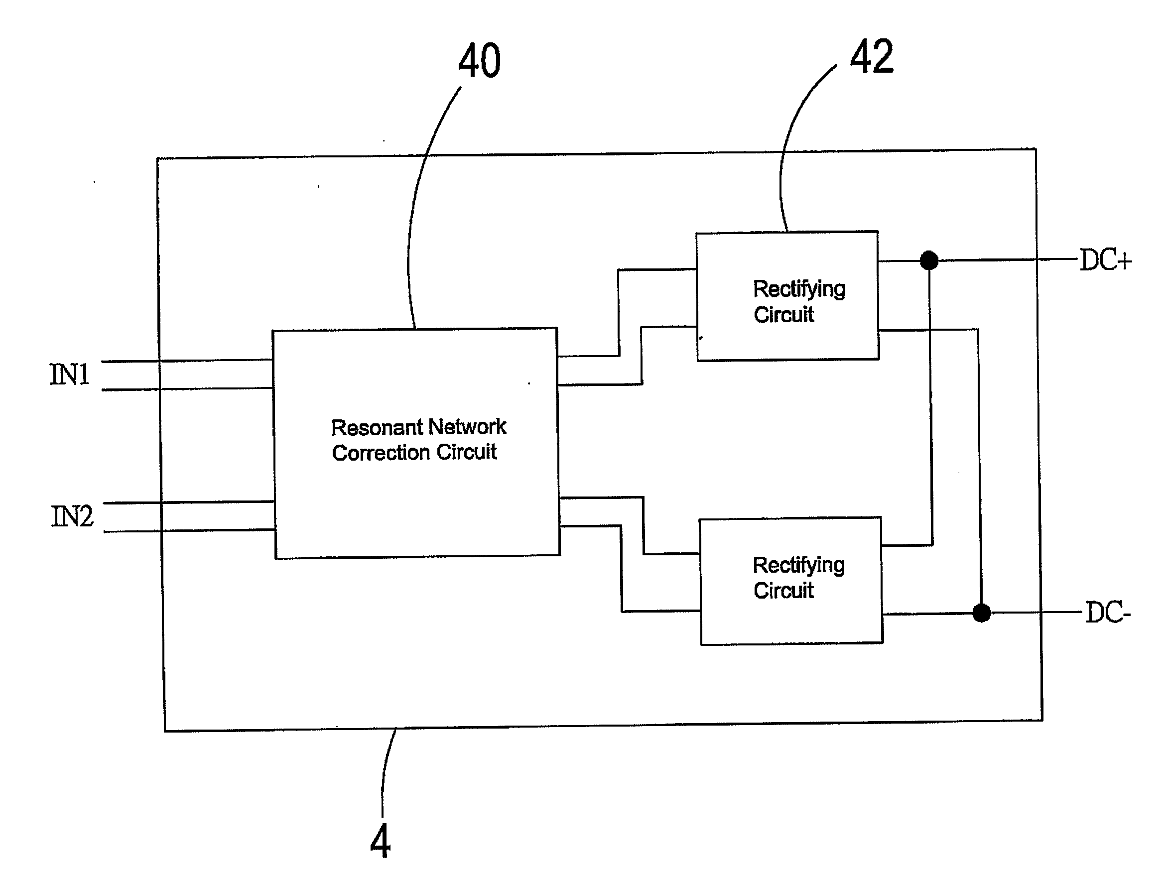
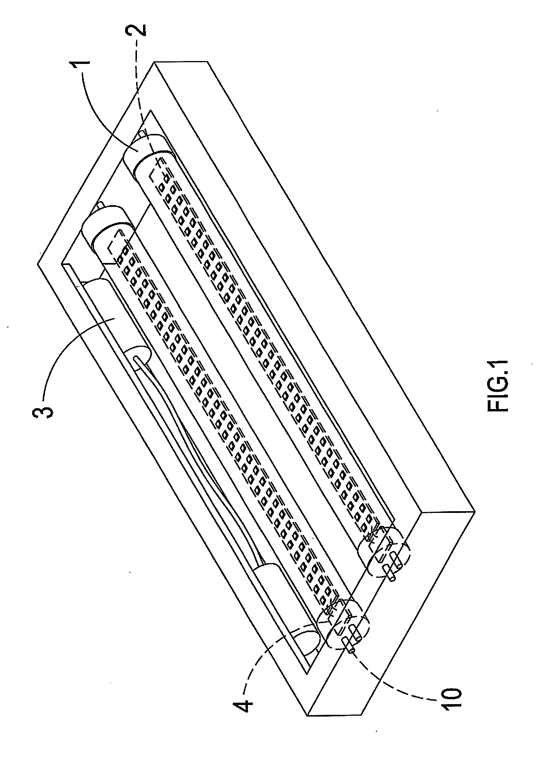
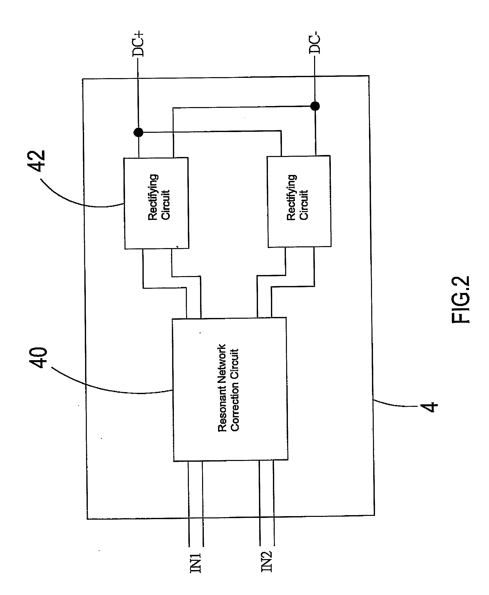
[0014]Referring to FIG. 1 and FIG. 2, it shows a three-dimensional schematic view and a block diagram, of a preferred embodiment of the present invention. As shown in the drawings, the present invention is an LED drive circuit device, wherein LEDs 2 are installed in a lamp-set 1 and two ends of the lamp-set 1 are provided respectively with two pins 10 to receive a high frequency AC outputted from a ballast 3, with the two pins 10 being further electrically connected with a drive circuit module 4. The drive circuit module 4 is primarily composed of a resonant network correction circuit 40 and a rectifying circuit 42, wherein the resonant network correction circuit 40 can adjust the high frequency AC received from the two pins 10 to comply with an application range of LED current and then the rectifying circuit 42 will convert the AC into a DC which is next outputted through other two pins 10.

[0015]Referring to FIG. 3, it shows a schematic view of a usage state of the present inventio...


PUM


Abstract

The present invention discloses an LED drive circuit device. The LEDs are installed in a lamp-set and two ends of the lamp-set are provided respectively with two pins to receive a high frequency AC outputted from a ballast, with the two pins being further electrically connected with a drive circuit module. The drive circuit module includes primarily a resonant network correction circuit and a rectifying circuit. The resonant network correction circuit adjusts the high frequency AC received by the two pins to comply with an application range of LED current and then the rectifying circuit converts the AC into a DC which is next outputted through other two pins. By applying the aforementioned circuits, the LED lamp-set can be applied to an ordinary electronic ballast, thereby achieving high compatibility.

Description

BACKGROUND OF THE INVENTION[0001]a) Field of the Invention[0002]The present invention relates to an LED (Light Emitting Diode) lamp-set and more particularly to an LED drive circuit device which can be applied to any ballast and is highly compatible.[0003]b) Description of the Prior Art[0004]Energy saving has already been a goal to be advocated by every country for many years, as energy saving can achieve objects of protecting environment and not wasting resources. Electric energy is one of the energy sources which are consumed the most; staples, lighting equipment and household appliances should all be driven to operate through the electric energy. Particularly, companies should turn on the lighting equipment day and night to allow staffs to work efficiently; whereas, the lighting equipment used by a general company utilizes a ballast to ignite a lamp tube for illumination, wherein a conventional mercury lamp tube uses a conventional ballast to ignite, thereby achieving the illumin...

Claims


Application Information

Patent Timeline
IPC IPC(8): H05B37/02
CPCH05B33/0815H05B33/0803H05B45/30H05B45/357
Inventor CHEN, WEN-SHEN
Owner ARTEAST TECH CORP
Why Eureka
Try Eureka