
Multi-position synchronous thermal shrinkage wiring harness thermal shrinkage equipment, integrated device and method

A multi-position, heat-shrinking technology, which is applied in the assembly/disassembly of contacts, vehicle connectors, connection insulation, etc., can solve the problems of large position changes of the second heat-shrinkable tube b and differences in heat-shrinking process, and achieve adaptability Strong performance, efficient heat shrinkage, and convenient adjustment

Pending Publication Date: 2020-06-16
ZHUJI CANU AUTOMATION EQUIP CO LTD
View PDF0 Cites 1 Cited by
  • Summary
  • Abstract
  • Description
  • Claims
  • Application Information

AI Technical Summary

Problems solved by technology

Generally, the position of the heat-shrinkable tube a at the head is relatively fixed, and the position of the second heat-shrinkable tube b changes greatly; and the two heat-shrinkable tubes are different, and their heat-shrinking processes are different

Method used


Image

  • Multi-position synchronous thermal shrinkage wiring harness thermal shrinkage equipment, integrated device and method
  • Multi-position synchronous thermal shrinkage wiring harness thermal shrinkage equipment, integrated device and method
  • Multi-position synchronous thermal shrinkage wiring harness thermal shrinkage equipment, integrated device and method

Examples


Embodiment Construction

[0047] The present invention will be further elaborated and illustrated below in conjunction with the accompanying drawings and specific embodiments. The technical features of the various implementations in the present invention can be combined accordingly on the premise that there is no conflict with each other.

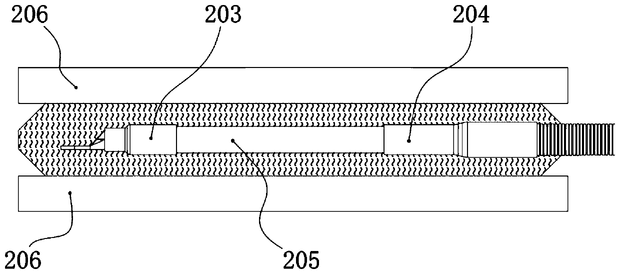
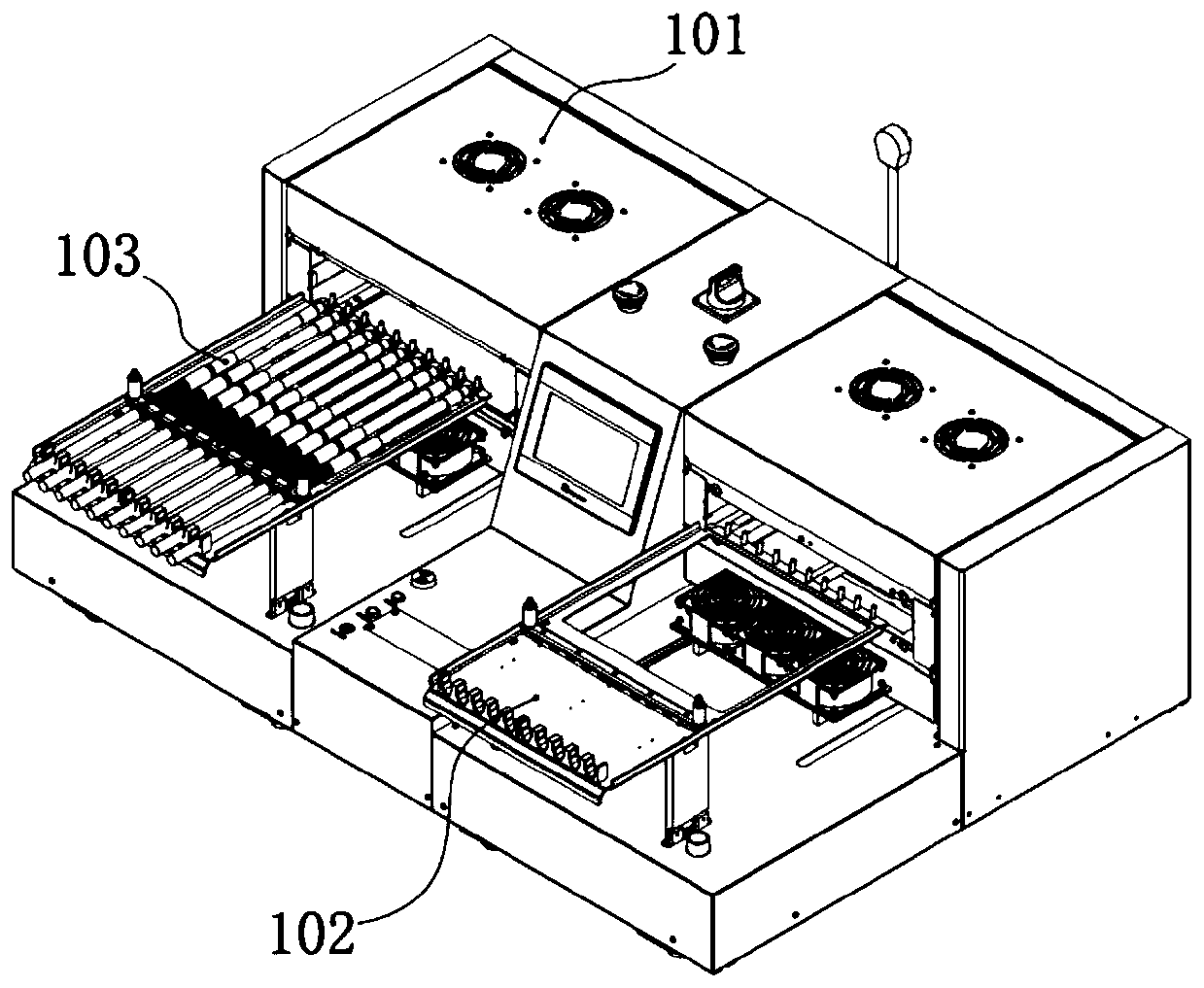
[0048] Such as figure 1 As shown in the figure, for the sake of easy understanding, a structural form of the heat-shrinkable wire harness is shown, which is a common form in new energy vehicles. In the wire harness, one end is a metal terminal 001, which is combined with one end of the wire harness body, and the other end of the wire harness body is connected and fixed with a corrugated tube 002. Therefore, in this kind of wire harness, two heat-shrinkable tubes generally need to be installed along the wire harness: one heat-shrinkable tube a203 is used for the protection of the joint between the wire harness body and the metal terminal 001, and the other heat-shri...


PUM


Abstract

The invention discloses multi-position synchronous thermal shrinkage wiring harness thermal shrinkage equipment, an integrated device and a method, and belongs to the field of automatic wiring harnessgeneration equipment. According to the invention, accurate thermal shrinkage can be carried out on a wire harness with a plurality of thermal shrinkage tubes through the plurality of groups of heating assemblies, and parameters can be set independently; compared with the existing scheme of only increasing the coverage size of heating plates in the market, the provided scheme can ensure that thermal shrinkage of different thermal shrinkage tubes can be carried out according to different process requirements, and meanwhile, the wire harness rubber skin can be prevented from being directly baked; therefore, the whole equipment is more energy-saving and environment-friendly, and the equipment has very strong adaptability to the size and process of the wire harness and very high compatibility.A distance adjusting part assembly can be further added to the heating assemblies, so that the distance between the heating plates can be adjusted autonomously and conveniently. Through the improvement, the optimal distance of the heating plates can be adjusted according to the maximum outer diameters of different wire harnesses, so that the heat absorption effect of the thermal shrinkage tubes reaches the optimal state, and the thermal shrinkage of the thermal shrinkage tubes is more efficient.

Description

technical field [0001] The invention belongs to the field of heat-shrinkage automation equipment for heat-shrinkage tubes in wire harness production, and in particular relates to a heat-shrinkage automation equipment for one-time completion of heat-shrinkage protection with one or more heat-shrinkage tubes at the end of a wire harness. Background technique [0002] In the field of wire harness production, in actual production, one or several kinds of wires (or metal terminals) are connected together by peeling, welding, riveting and other processes to form the finished wire harness required by customers. In this process, wires and wires, wires The connection with metal terminals needs to be protected to achieve insulation and other purposes. Heat-shrinkable tube heat-shrinkable protection is an important and common protection method used in this link, and it also has a binding effect. The heat shrinkable position of the heat shrink tube is at or near one end of the wire, wh...

Claims


Application Information

Patent Timeline
IPC IPC(8): H01R43/20H01R4/72
CPCH01R4/72H01R43/20H01R2201/26
Inventor 汤列郭逸恺
Owner ZHUJI CANU AUTOMATION EQUIP CO LTD
Learn More