Multiband multifilar antenna

a multi-filar antenna and antenna technology, applied in the direction of antennas, non-resonant long antennas, electrical devices, etc., can solve the problems of inability to meet the needs of the user, the design of the matching network can be quite challenging, and the use of multiple antennas, besides being impractical in many cases, is unacceptabl

Active Publication Date: 2011-10-20
MAXTENA
View PDF9 Cites 27 Cited by
  • Summary
  • Abstract
  • Description
  • Claims
  • Application Information

AI Technical Summary

Problems solved by technology

The design of the matching network can be quite challenging because the strong coupling between the different arms requires that the four ports are matched simultaneously.
Using multiple antennas, besides b

Method used


Image

  • Multiband multifilar antenna
  • Multiband multifilar antenna
  • Multiband multifilar antenna

Examples


Embodiment Construction

As required, detailed embodiments of the present invention are disclosed herein; however, it is to be understood that the disclosed embodiments are merely exemplary of the invention, which can be embodied in various forms. Therefore, specific structural and functional details disclosed herein are not to be interpreted as limiting, but merely as a basis for the claims and as a representative basis for teaching one skilled in the art to variously employ the present invention in virtually any appropriately detailed structure. Further, the terms and phrases used herein are not intended to be limiting; but rather, to provide an understandable description of the invention.

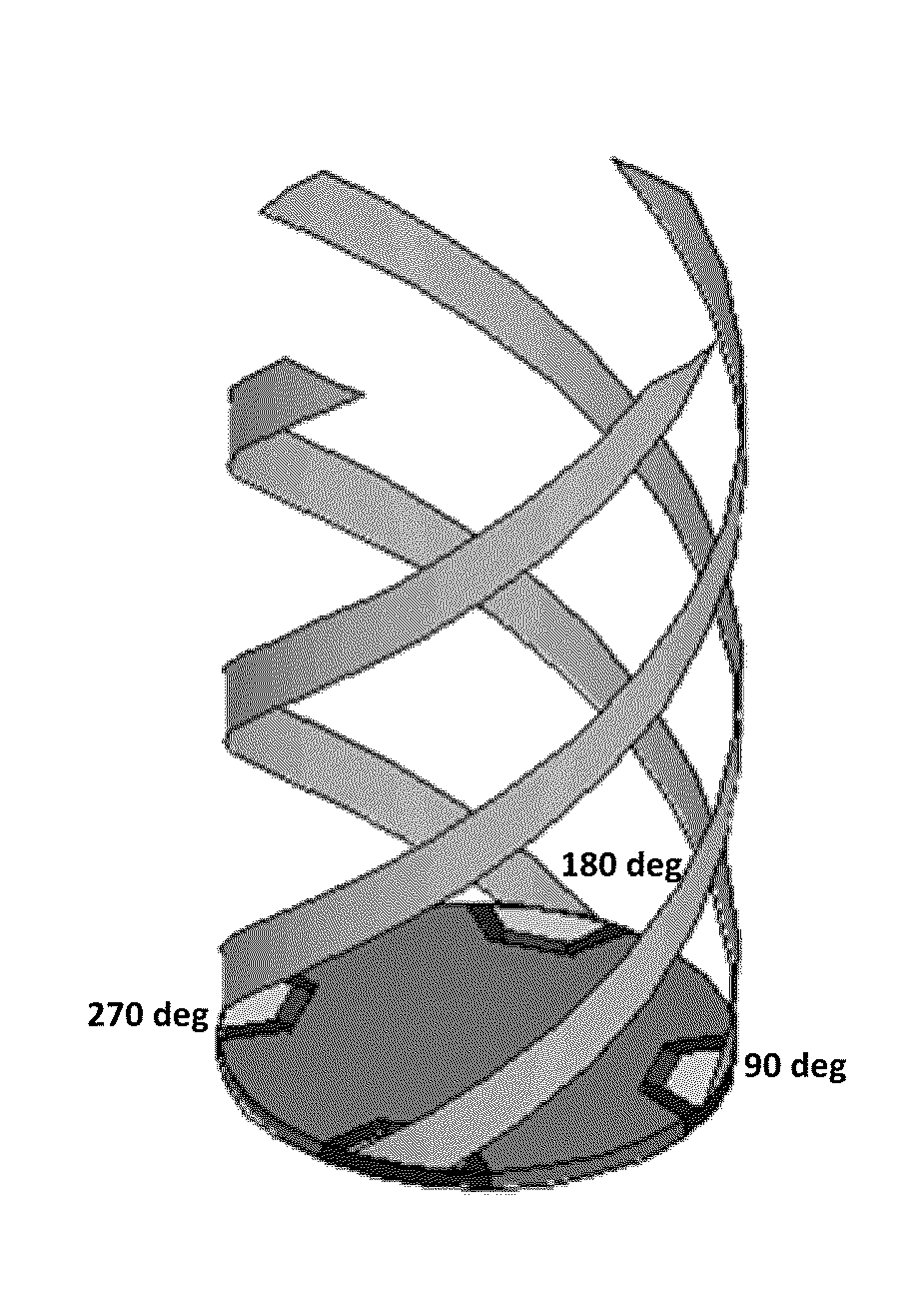
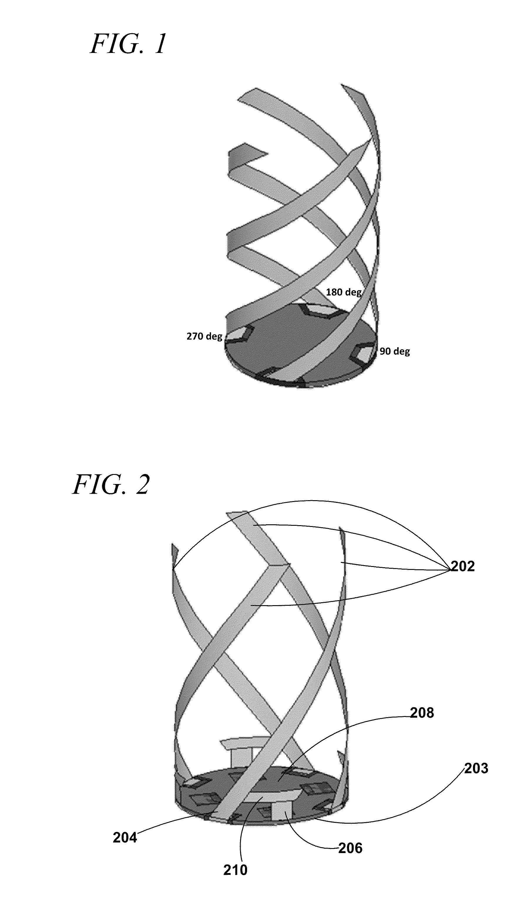
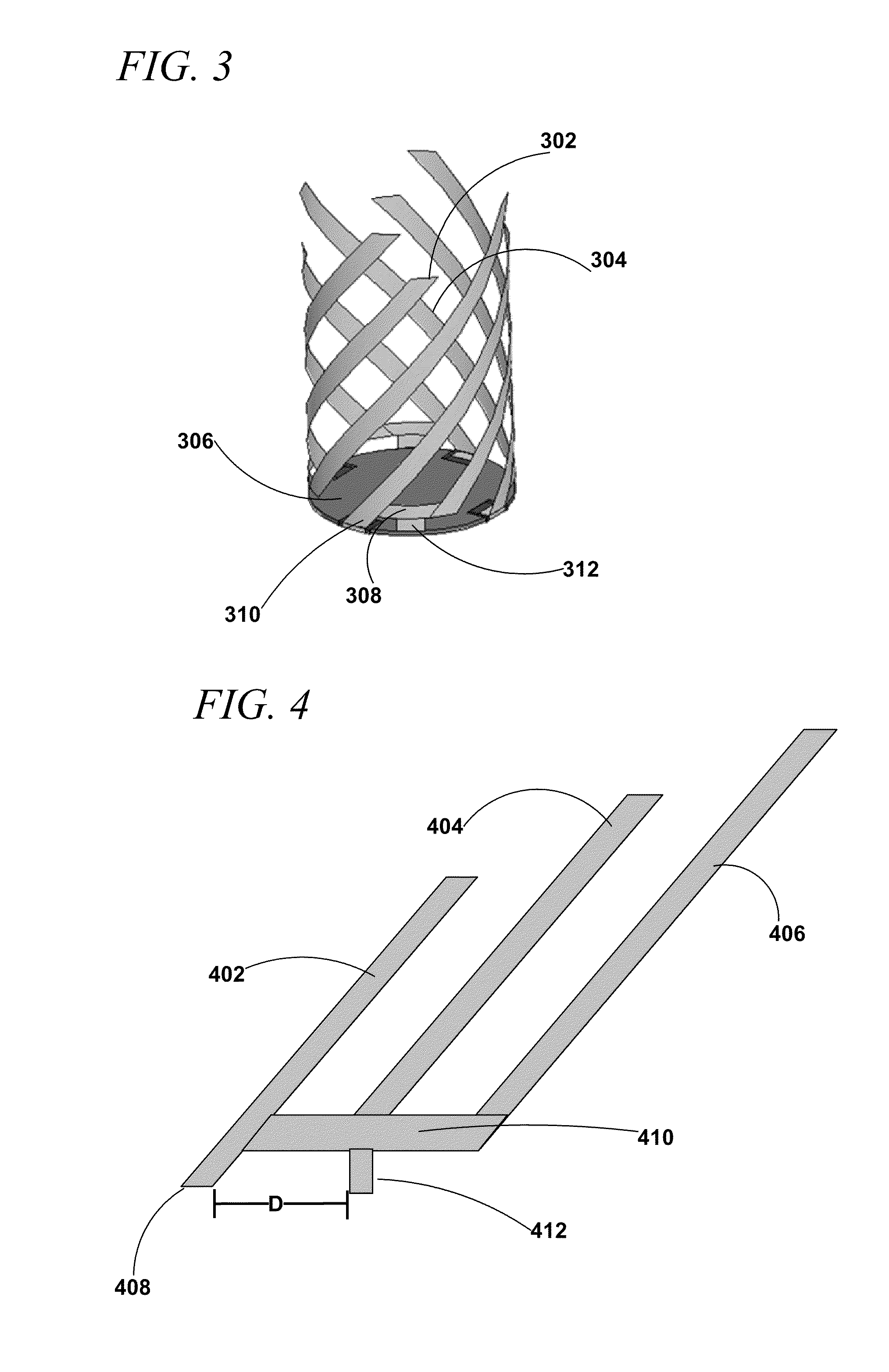
According to the present invention compact quadrifilar antennas that do not require external matching are provided. Moreover according to embodiments of the invention multifilar antenna structures that provide multiband coverage while being fed like traditional QHA are provided. In each band multiband antennas according ...


PUM


Abstract

Multi-band quadrifilar antennas that are suitable for satellite communication include composite elements each of which include multiple conductors operating at different frequencies connected to a bus bar. Each composite element is coupled to a signal feed and to a ground structure.

Description

BACKGROUND OF THE INVENTION1. Field of the InventionThe present invention relates to the field of compact multiband antennas for satellite aided navigation and mobile satellite communications.2. Description of Related ArtCurrently in the mobile satellite communication and global navigation industries there is a need for compact multiband antennas that can be easily integrated into portable devices or more generally into mobile platforms and equipment. Ideally such antennas should provide a very controlled radiation pattern, with uniform coverage of the upper hemisphere and circular polarization purity, for multipath and noise rejection. The ideal antenna should also be electromagnetically isolated from the chassis or external conductive ground structures that it is mounted on, to enable integration on multiple platforms with minimal redesign.The fractional-turn Quadrifilar Helix Antenna (QHA) disclosed in US Patent Application Publication 2008 / 0174501 A1 assigned in common with the ...

Claims


Application Information

Patent Timeline
IPC IPC(8): H01Q21/00
CPCH01Q11/08
Inventor DINALLO, CARLO
Owner MAXTENA
Why Eureka
Try Eureka