Dental fulcrum wrench

a fulcrum wrench and tooth technology, applied in the field of dental and surgical tools, can solve the problems of inadvertent damage to neighboring teeth, relatively high risk of inadvertent bone fracture, etc., and achieve the effects of less control, easy operation, and adjustment of the tightness of the invention

Inactive Publication Date: 2011-10-20
KATZ HOWARD IAN
View PDF8 Cites 12 Cited by
  • Summary
  • Abstract
  • Description
  • Claims
  • Application Information

AI Technical Summary

Benefits of technology

[0013]In some embodiments, the invention will also have force measuring devices or gauges attached which will assist the dentist in determining the optimum amount of force or pressure to apply to the device—that is, an amount of force or pressure adequate to loosen the selected tooth without breaking the bone in which the tooth is embedded.
[0017]Thus among the various advantages of the invention disclosed herein versus prior art dental forceps devices is the advantage of the elimination of the need for the user to squeeze the device tightly using his or her hands. Such squeezing is undesirable, because there is less control when the user has to squeeze, and at the same time the squeezing action by the wrist tends to force prior art forceps in a downward direction even when this direction is not desired. Further, the elimination of the multiple divergent handles of the prior art forceps design makes the invention easier to operate by weaker and smaller dentists. That is, much less force is necessary when using the invention.
[0018]The thumbscrew allows the user to adjust the tightness of the invention while simultaneously holding the handle with the same hand. This configuration has advantages over alternative wrench designs that may have the tightening apparatus at the back of the wrench, thus requiring two hands to operate optimally.

Problems solved by technology

This process has the drawbacks of requiring that the dentist have a significant amount of physical hand strength, and the process also creates a relatively high risk of inadvertent bone fracture due to the high amount of force required to extract the tooth.
Here elevator tools may be used for this purpose, but these tools may have the drawback of inadvertently causing damage to these neighboring teeth.

Method used


Image

  • Dental fulcrum wrench
  • Dental fulcrum wrench
  • Dental fulcrum wrench

Examples


Embodiment Construction

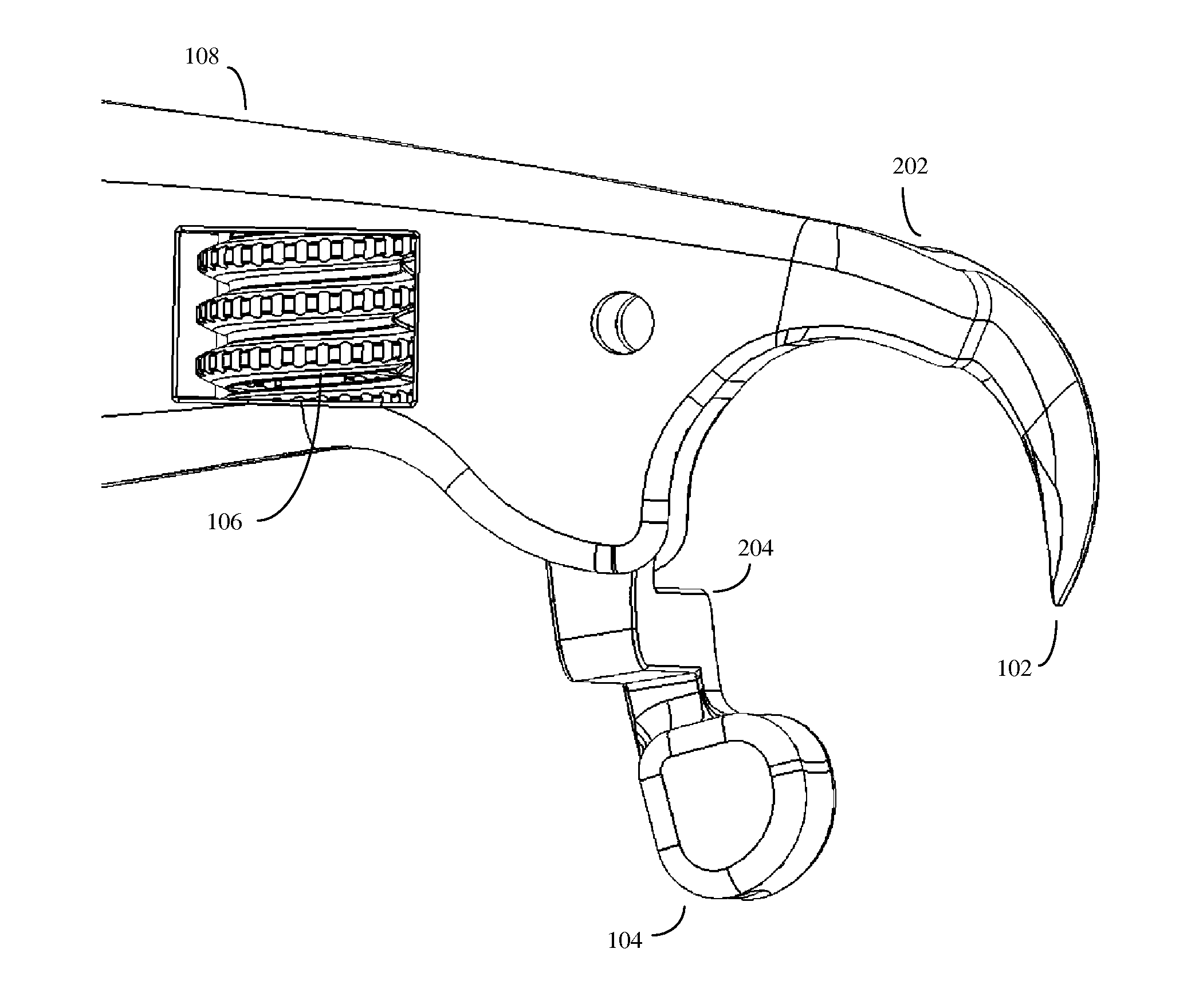
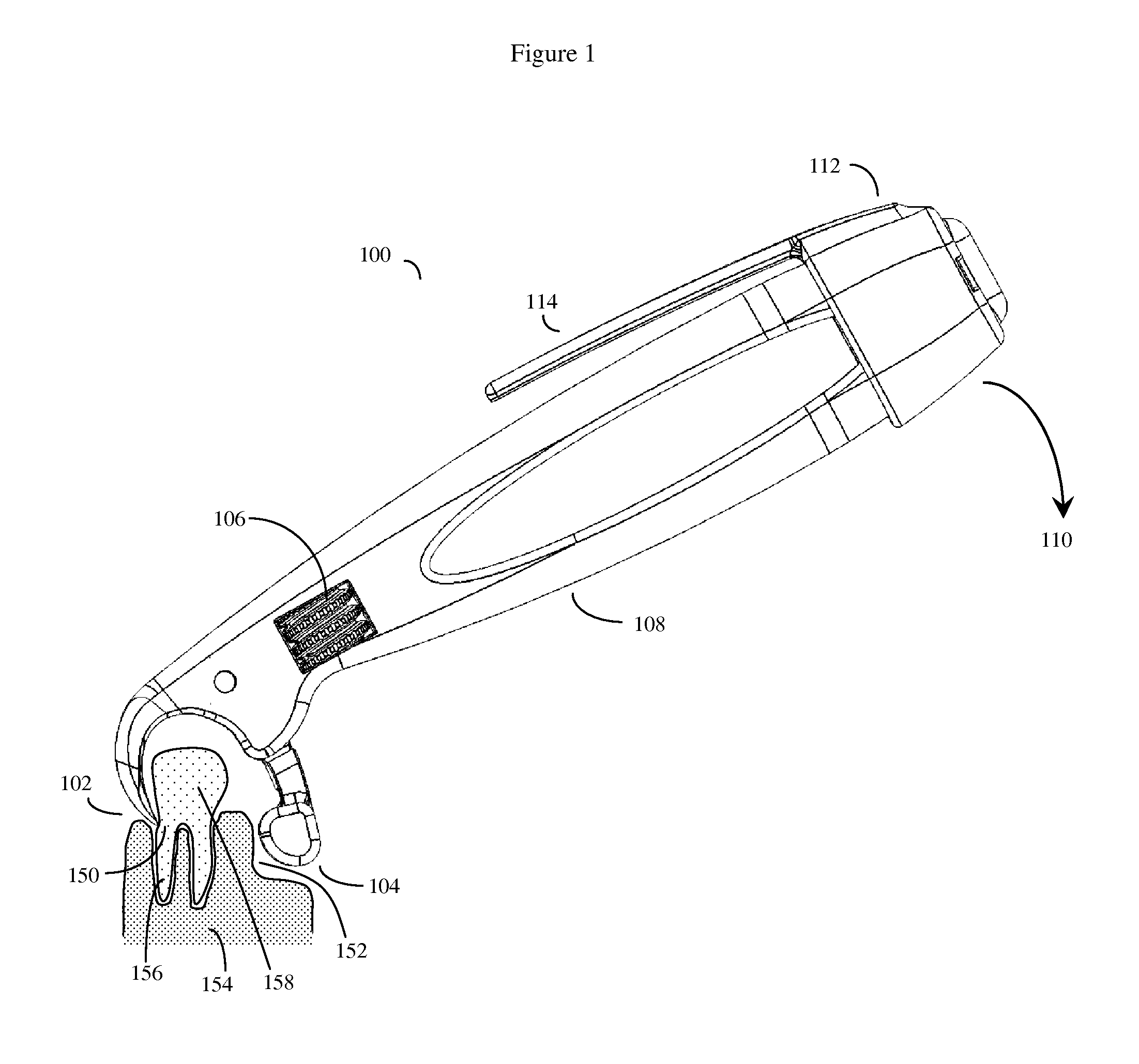
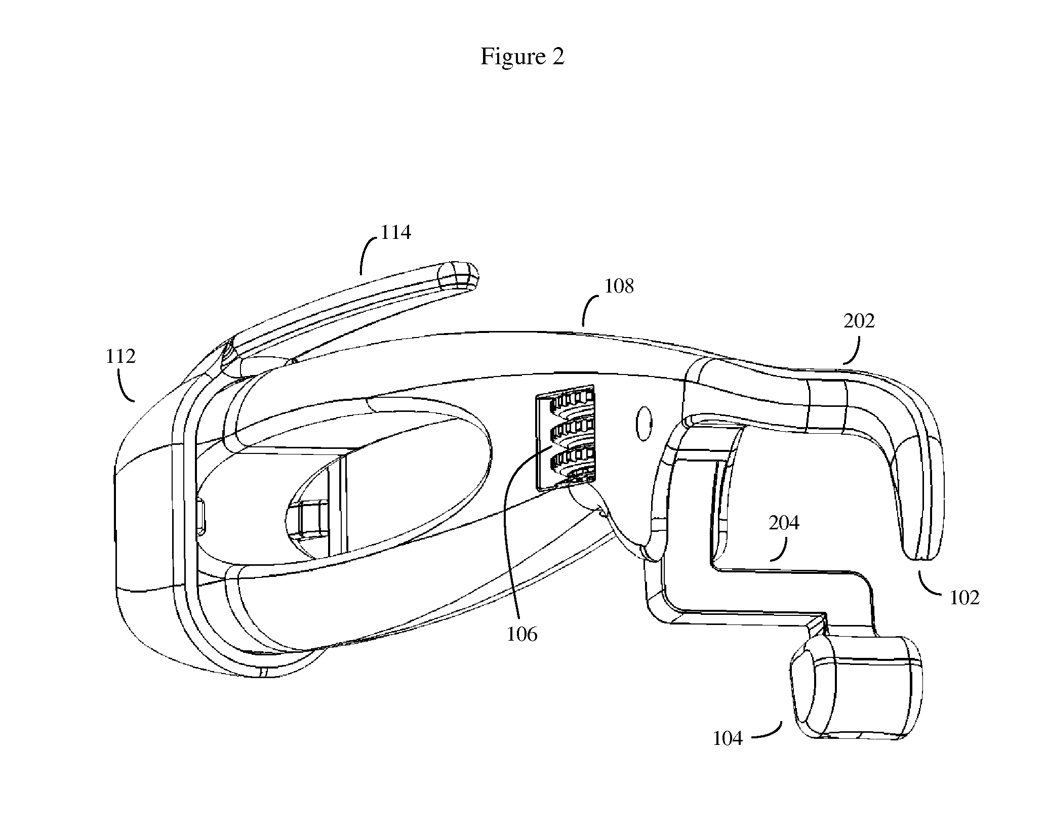
[0030]The device works by first positioning a fixed terminating sharpened end of a crescent wrench-like appliance along the tooth root surface of a selected tooth below the gum line. Then a second movable jaw of the device is positioned against the opposing facing side of the same tooth projecting from the gum line, and tightened about the tooth using a thumbscrew or other jaw movement interface device. When in position, the device functions as a single handled lever, and acts as a fulcrum forcing the tooth away from the patient's gum line. This forcibly dislodges the tooth from the patient's gum line and bone, in the direction of the applied force.

[0031]The forces engaged are similar to the effects of a dental elevator. In a dental elevator, the tooth is pried loose by using the smooth rounded surface of the back of the blade of the dental elevator as a fulcrum against the bone supporting the tooth to be extracted.

[0032]Where not otherwise specified, the device will often be constr...


PUM


Abstract

A dental wrench device to loosen and extract teeth, comprising a handle with a fixed tapered jaw. A moveable jaw is also coupled to the handle. The tapered jaw is positioned along the root of a tooth selected to be extracted. The moveable jaw has a blunt contoured shape configured to grasp the gum and bone on the opposite side of the selected tooth at a level below the crown of the tooth. The device is applied and tightened around the selected tooth by turning a thumbscrew, or other jaw movement interface, that moves the moveable jaw end closer to the fixed tapered jaw end until the tooth is tightly gripped by the device. Once the wrench is locked into position, force may then be applied to extract the tooth. The device may also incorporate an optional force feedback gauge to warn the operator when excessive force is being applied.

Description

CROSS REFERENCE TO RELATED APPLICATIONS[0001]This application claims the priority benefit of U.S. Provisional Application No. 61 / 325,514, filed on Apr. 19, 2010, entitled “A wrench to loosen and extract teeth”, Howard Katz inventor.BACKGROUND OF THE INVENTION[0002]1. Field of the Invention[0003]The invention is in the general field of dental and surgical tools.[0004]2. Description of the Related Art[0005]Traditionally, tooth extraction has been an arduous process in which the first and second jaws of dental pliers or forceps are used to grasp onto opposite sides of a tooth above the gum line. The dentist will then both wiggle the tooth, and apply sufficient withdrawing force to pull the tooth out of the socket. This process has the drawbacks of requiring that the dentist have a significant amount of physical hand strength, and the process also creates a relatively high risk of inadvertent bone fracture due to the high amount of force required to extract the tooth.[0006]A number of d...

Claims


Application Information

Patent Timeline
Patent Type & Authority Applications(United States)
IPC IPC(8): A61C3/14
CPCA61C3/14
Inventor KATZ, HOWARD IAN
Owner KATZ HOWARD IAN
Why Eureka
Try Eureka