
Protective mask for the practice of outdoor sports

a mask and outdoor sports technology, applied in the field of protective masks, can solve the problems of limiting the viewing angle of the entire field of vision, affecting the field of vision/space requirement ratio of the mask, and accentuate the problem of reduced field of vision,

Inactive Publication Date: 2011-10-27
SALOMON SA
View PDF7 Cites 22 Cited by
  • Summary
  • Abstract
  • Description
  • Claims
  • Application Information

AI Technical Summary

Benefits of technology

The invention is an eye protection mask for outdoor sports that has a unique lens design with two vision zones and a groove for the lens. The mask also has a deformable skirt and a frame with a conduit for air flow. The lens is snap-fitted into the groove of the frame and has two superimposed walls. The technical effects of the invention include improved protection against sun and wind, improved visibility, and improved air flow.

Problems solved by technology

The height and width of the frame thus limit the viewing angle of the entire field of vision.
The problem of reduced field of vision is accentuated when the mask is equipped with a double lens, or a double-walled lens, i.e., a front lens member and a rear lens member.
Therefore, the use of flexible materials for making the frame has a very negative effect on the field of vision / space requirement ratio of the mask.
Moreover, the vision of the user can also deteriorate because these deformations of the frame transferred to the lens, i.e., such deformations of the frame cause deformations of the lens.
An impact against the mask can also generate an excessive deformation of the lens resulting in its rupture, or cracking.
Moreover, such a mask does not allow sufficient removal of moisture from the lens, or eliminate fogging of the lens, especially when the ambient humidity is high or the user is perspiring profusely.
This is a particular problem when the user wears prescription eyeglasses that have not been treated against fogging.
Increasing the section of the air vents proportionately reduces the field of vision of the user, which may generate unpleasant cooling on the face of the user without providing any efficiency in evacuating water vapor.
Such fans however require a power supply, substantially weighing down the mask, substantially increasing the space requirement of the mask, and altering the field of vision that is provided.

Method used


Image

  • Protective mask for the practice of outdoor sports
  • Protective mask for the practice of outdoor sports
  • Protective mask for the practice of outdoor sports

Examples


Embodiment Construction

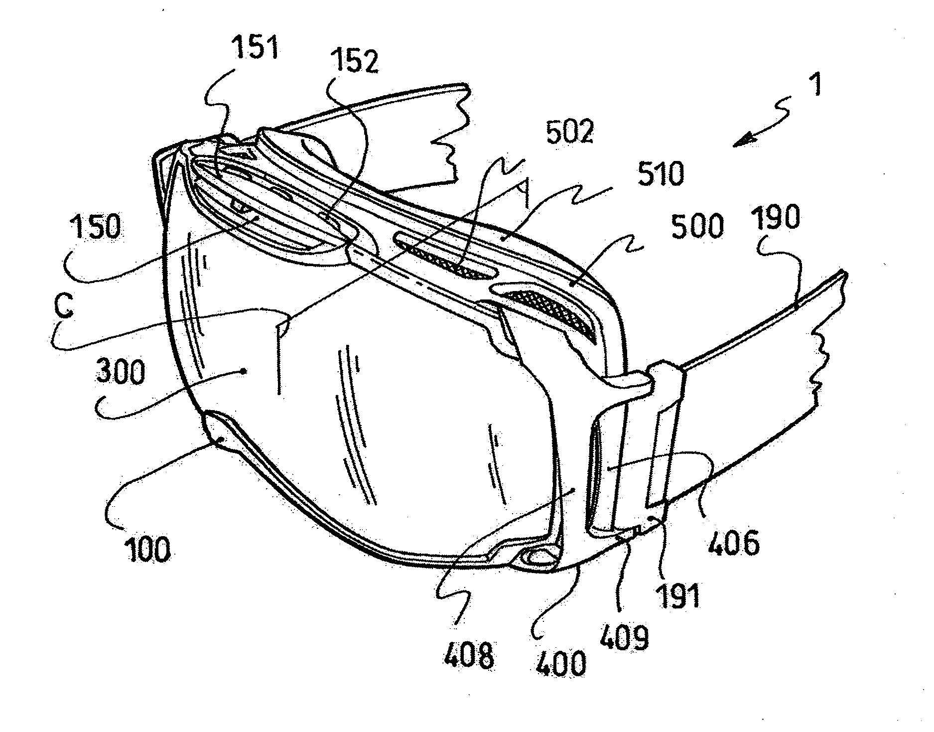
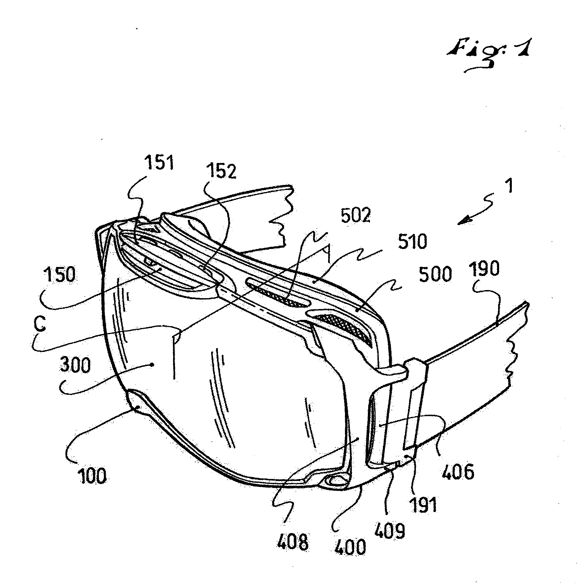
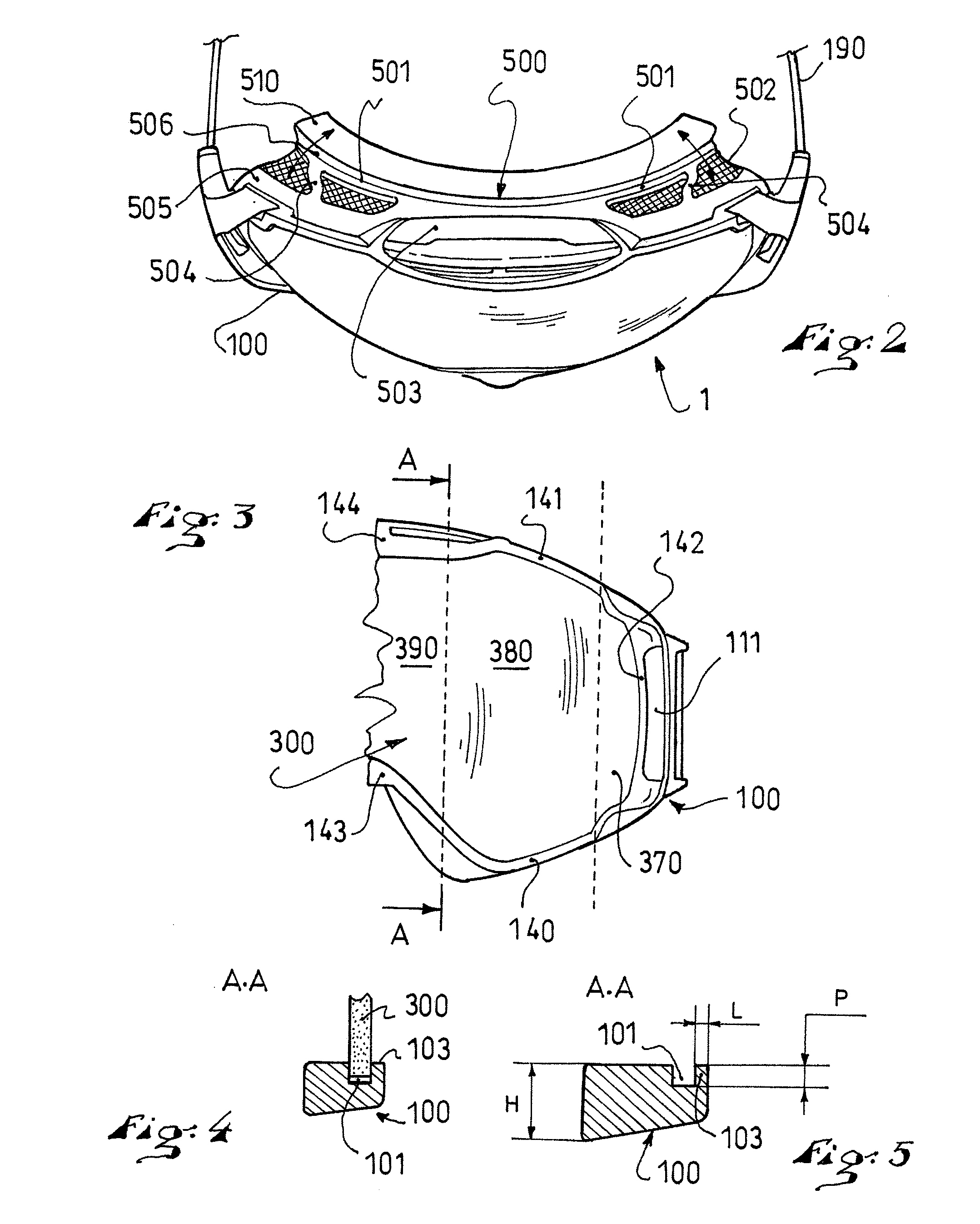
FIG. 1 is a perspective view of a mask 1 according to an embodiment of the invention. Although the term “mask” is used herein, the invention can be considered to relate to protective eyewear, or goggles, as well. FIG. 2 is a schematic top view of the mask 1. The mask 1 includes a peripheral frame 100. The frame 100 demarcates an opening 102, which is closed by an eye protection lens 300. The lens 300 is attached to the frame 100. A strap 190 is attached to the lateral ends of the mask 1. The strap 190 and frame 100 form a loop for surrounding the head of the user to ensure that it stays in place.

FIG. 3 is a front view of the left half of the frame 100 provided with the lens 300. The protective lens 300 closes, or blocks, the opening 102 in order to protect the user's eyes from external attacks, such as wind, snow, and / or water. The lens 300 is transparent and, in a known manner, can have light filtering properties in order to protect the user's eyes against solar radiation, for exam...


PUM


Abstract

The invention relates to an eye protection mask for the practice of outdoor sports, the mask including an eye protection lens having two vision zones, adapted to be positioned opposite the user's eyes when worn, and a median portion connecting the vision zones, and a peripheral frame demarcating an opening closed by the lens, the frame having a groove housing the edge of the lens, the frame being made of a rigid material and the groove having a depth of less than 2.5 mm along the vertical direction of the vision zones of the lens.

Description

CROSS-REFERENCE TO RELATED APPLICATIONThis application is based upon the French priority Patent Application No. 10.01728, filed Apr. 22, 2010, the disclosure of which is hereby incorporated by reference thereto, and the priority of which is hereby claimed under 35 U.S.C. §119.BACKGROUND OF THE INVENTION1. Field of the InventionThe invention relates to protective masks, in particular protective masks for the practice of outdoor sports such as alpine skiing, mountain biking, and motocross. In more particular embodiments, the invention relates to protective eyewear, or goggles.2. Background InformationProtective masks, such as protective eyewear, or goggles, are typically used in the practice of certain outdoor sports to protect the user's eyes from wind, water, mud and / or solar radiation. The use of such masks is generally favored over sunglasses with fully rimmed frames because of the larger continuous field of vision they provide, especially in the median portion. Furthermore, the u...

Claims


Application Information

Patent Timeline
Patent Type & Authority Applications(United States)
IPC IPC(8): A61F9/02
CPCA61F9/028A61F9/027
Inventor RENAUD-GOUD, GILLESVERHAEGHE, QUENTIN
Owner SALOMON SA
Learn More