
Thermoacoustic engine

a technology of thermoacoustic engines and exhaust heat recovery, which is applied in the direction of stirling engines, machines/engines, hot gas positive displacement engine plants, etc., can solve the problems of inability to efficiently recover exhaust heat from conventional thermoacoustic engines, and the temperature of exhaust heat is not constant, so as to achieve the effect of increasing heat recovery efficiency

Inactive Publication Date: 2011-10-27
HONDA MOTOR CO LTD
View PDF4 Cites 2 Cited by
  • Summary
  • Abstract
  • Description
  • Claims
  • Application Information

AI Technical Summary

Benefits of technology

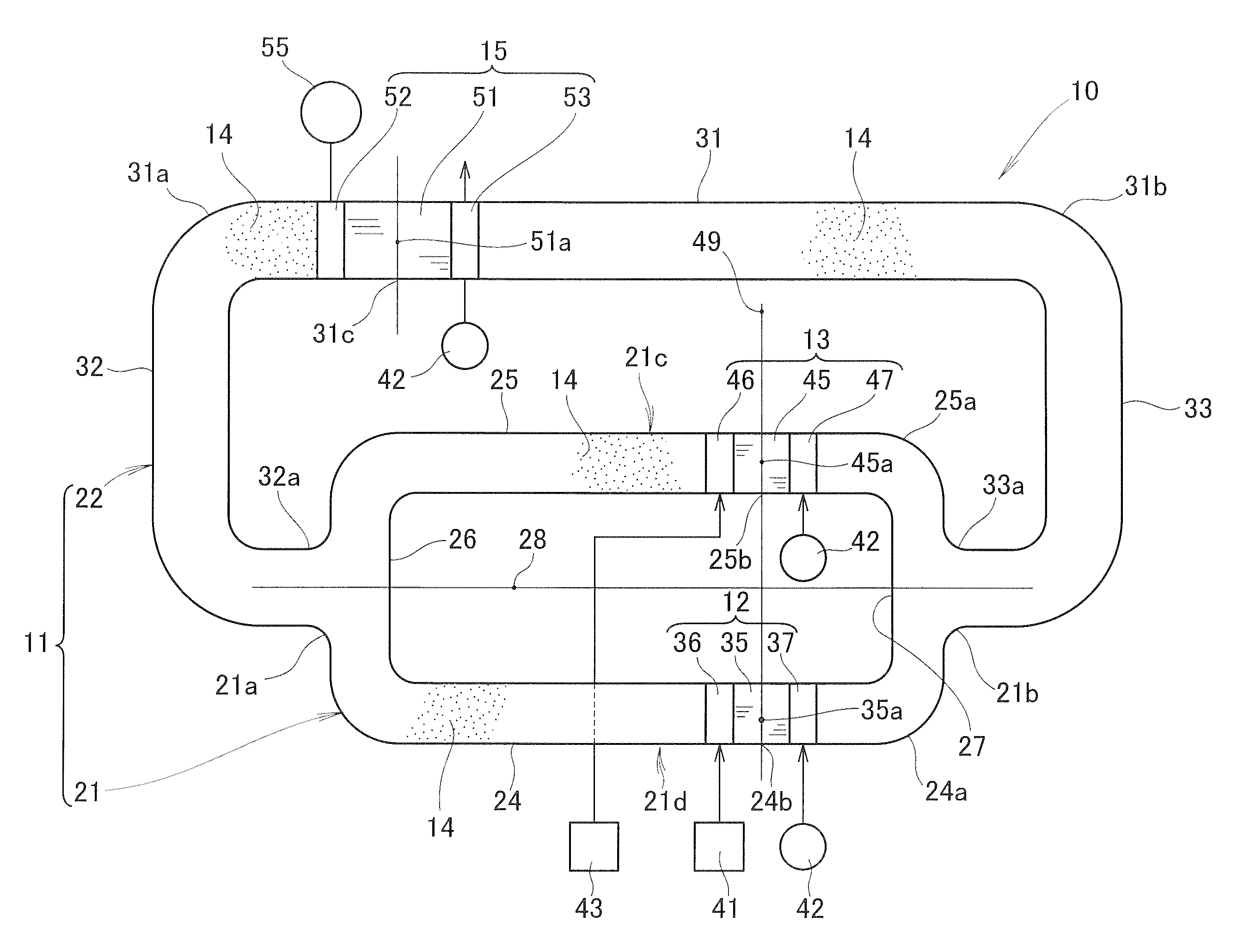
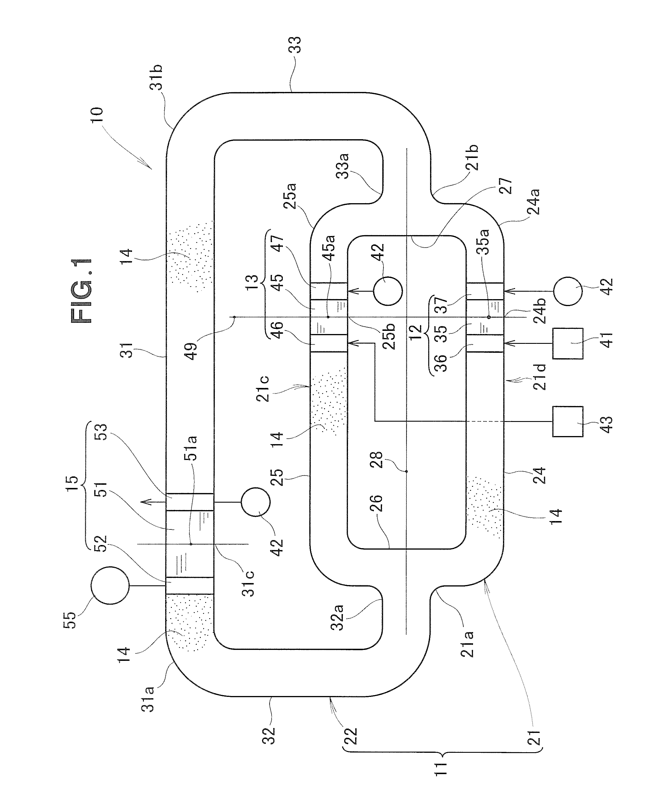
[0008]With the thermoacoustic engine thus arranged, a sound wave (acoustic power) induced by one stack and a sound wave (acoustic power) induced by another stack are synthesized without attenuation while the respective sound waves are propagating to the heat storage unit. The heat storage unit is thus able to recover heat with increased efficiencies. The thermoacoustic engine equipped with two or more stacks can be used in combination with a corresponding number of heat sources of different temperatures.

Problems solved by technology

However, such exhaust heats are not constant in temperature.
Furthermore, if the exhaust heat is near room temperature, efficient recovery of the exhaust heat by the conventional thermoacoustic engine is practically impossible.

Method used


Image

  • Thermoacoustic engine
  • Thermoacoustic engine
  • Thermoacoustic engine

Examples


first embodiment

[0015]A thermoacoustic engine according to the present invention will be described below with reference to FIG. 1. As shown in this figure, the thermoacoustic engine 10 takes the form of a looped tube type thermoacoustic engine and comprises an endless or looped tube 11 filled with a gas 14, first and second thermal acoustic generators 12 and 13 disposed in parallel in the looped tube 11 and operable to induce a sound wave (acoustic oscillations of the gas) when supplied with external heat at one end thereof, and a heat storage unit 15 disposed in the looped tube 11 and adapted to be cooled or heated by the sound wave propagating from the generators 12, 13 to the heat storage unit 15.

[0016]The looped tube 11 is a circular cross-section tube made of stainless steel and filled with an inert gas, such as nitrogen, helium, argon, or a mixture of helium and argon. The looped tube 11 is comprised of a generator-side looped tube section 21 of a substantially rectangular frame-shaped config...

second embodiment

[0052]Next, a thermoacoustic engine 60 according to the present invention will be described below with reference to FIG. 4. In the thermoacoustic engine 60, these parts which are identical or similar to those described above with respect to the thermoacoustic engine 10 are designated by the same reference characters and a further description can be omitted.

[0053]As shown in FIG. 4, the thermoacoustic engine 60 is structurally the same as the thermoacoustic engine 10 of the first embodiment but differs therefrom in that a single heat source 62 such as an internal combustion engine is used in place of the two heat sources 41 and 43. The heat source 62 is connected to a first hot-side heat exchanger 36 and a second hot-side heat exchanger 46. The first hot-side heat exchanger 36 is heated to a high temperature by heat supplied from the heat source 62. Similarly, the second hot-side heat exchanger 46 is heated to the high temperature by heat supplied from the heat source 62.

[0054]As a p...


PUM


Abstract

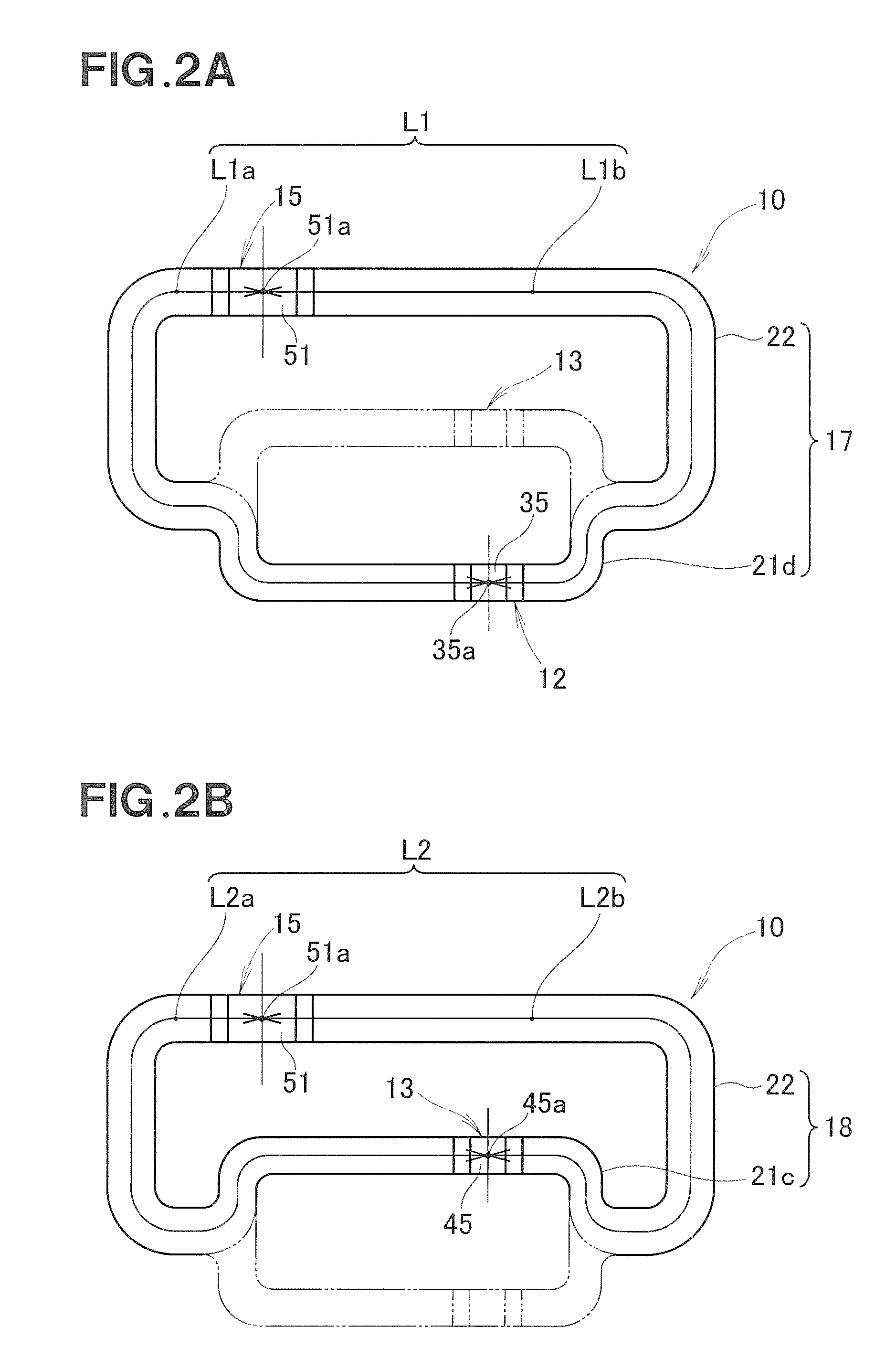
A thermoacoustic engine includes first and second stacks disposed in parallel in a looped tube and a heat storage unit disposed in the looped tube. A circuit length between a center of the first stack and a center of the heat storage unit is equal to a circuit length between a center of the second stack and the center of the heat storage unit. A first acoustic circuit including the first stack and the heat storage unit has a circuit length which is equal to a circuit length of a second acoustic circuit including the second stack and the heat storage unit.

Description

FIELD OF THE INVENTION[0001]The present invention relates to a thermoacoustic engine including a gas-filled looped tube having a stack and a heat storage unit embedded therein for recovering heat inputted to one end of the stack by the heat storage unit via a sound wave induced by the stack and propagating to the heat storage unit.BACKGROUND OF THE INVENTION[0002]Thermoacoustic engines are known as a device for recovering heat (exhaust heat) of a heat source. A typical example of such known thermoacoustic engines is disclosed in Japanese Patent Application Laid-Open Publication (JP-A) No. 2000-88378. The disclosed thermoacoustic engine includes a stack and a heat storage unit that are embedded in a gas-filled looped tube, and a hot-side heat exchanger and a cold-side heat exchanger that are disposed on opposite sides of each of the stack and the heat storage unit.[0003]In order to recover exhaust heat from a heat source, the hot-side heat exchanger associated with the stack is heate...

Claims


Application Information

Patent Timeline
Patent Type & Authority Applications(United States)
IPC IPC(8): F02G1/04
CPCF02G2243/54F02G1/04
Inventor NAKAMURA, HARUO
Owner HONDA MOTOR CO LTD
Learn More