Heat recovery apparatus and heat recovery method

Inactive Publication Date: 2010-10-14
MITSUBISHI HEAVY IND LTD +1
View PDF3 Cites 18 Cited by
  • Summary
  • Abstract
  • Description
  • Claims
  • Application Information

AI Technical Summary

Benefits of technology

[0025]The present invention provides a heat recovery apparatus and a heat recovery method which are capable of effectively

Problems solved by technology

The warming adversely affects the global environment in a devastating way, causing serious results such as unusual weather, including heavy rainfall, flooding, and the like, sea-level rise due to disappearance of glaciers, and resultant submersion of islands.
From such viewpoints, measures to reduce CO2 emissions have internationally become an important and urgent issue.
Specifically, a CO2 recovery apparatus for a thermal power plant using coal or the like consumes a large amount of steam and a large amount of electricity, and hence causes a large reduction in power generation output.
In addition, the CO2 recovery apparatus itself generates a low level of but a large amount of heat as described above.
However, it turned out that this trial configuration has the following drawbacks and hence is not economical

Method used


Image

  • Heat recovery apparatus and heat recovery method
  • Heat recovery apparatus and heat recovery method
  • Heat recovery apparatus and heat recovery method

Examples


Embodiment Construction

[0029]Hereinafter, a heat recovery apparatus and a heat recovery method according to the present invention will be described with reference to embodiments shown in the attached drawings.

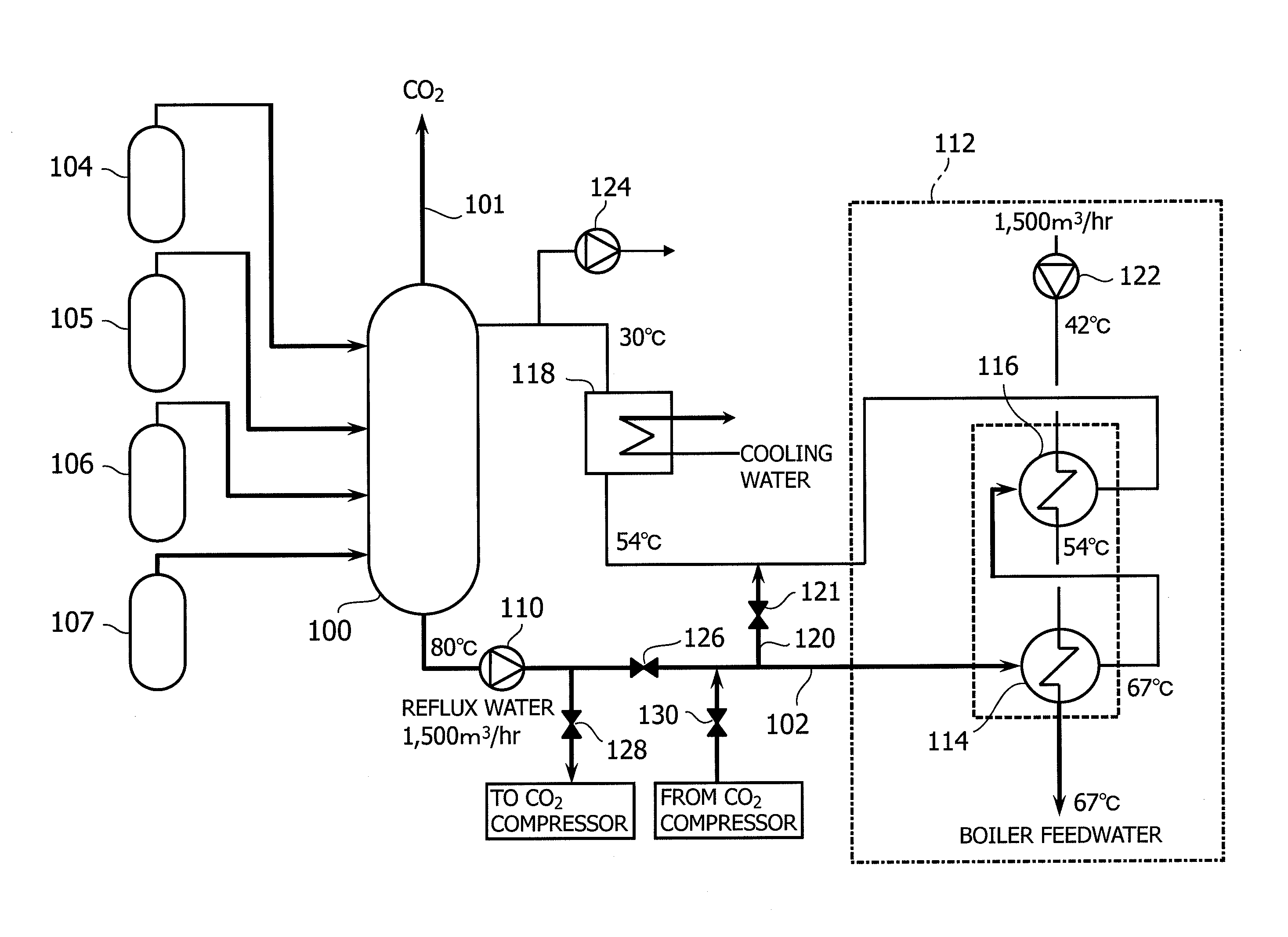
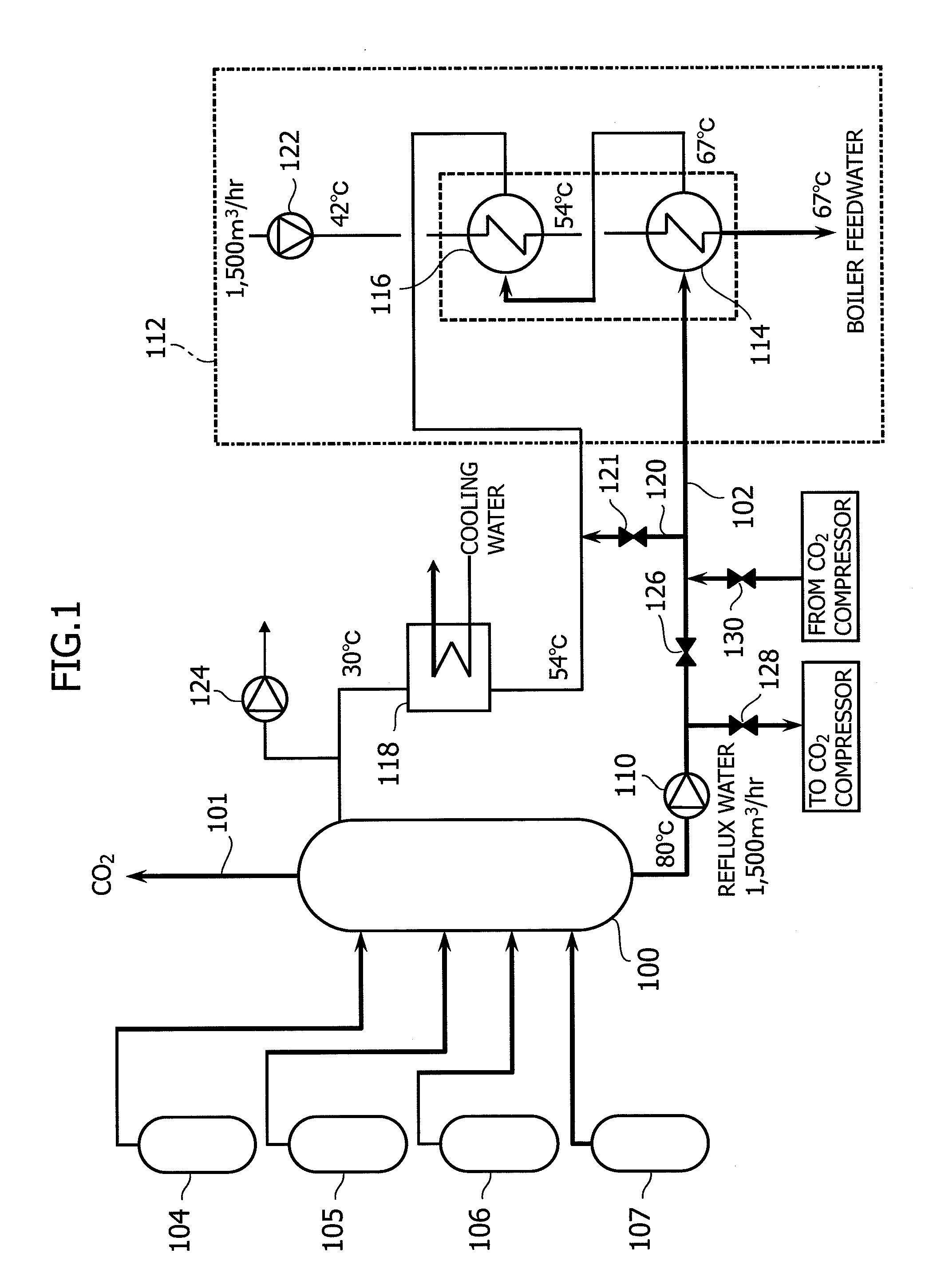
[0030]FIG. 1 shows an embodiment of the heat recovery apparatus according to the present invention.

[0031]The heat recovery apparatus according to the present invention includes a regeneration-tower-exit-CO2-gas cooling tower 100 and a circulation line 102, as essential components. In the following description, the regeneration-tower-exit-CO2-gas cooling tower 100 may be also referred to as a CO2 gas cooling tower 100.

[0032]In this embodiment, the CO2 gas cooling tower 100 is supplied with regeneration-tower-exit CO2 gas (hereinafter also referred to as CO2 gas) from four lines of regeneration towers 104 to 107.

[0033]The CO2 gas cooling tower 100 includes spray means, at an upper portion thereof, for supplying reflux water for cooling the regeneration-tower-exit CO2 gas. Moreover, the CO2 gas cooling ...


PUM


Abstract

A heat recovery apparatus, for an absorption apparatus for removing CO2 in combustion exhaust gas emitted from a thermal power plant 112 and for regeneration apparatuses 104 to 107 for regenerating CO2 in an absorbing liquid from the absorption apparatus, includes a regeneration-apparatus-exit-CO2-gas cooling apparatus 100 for cooling CO2 gas from an exhaust port of the regeneration apparatus, and may further include a circulation line 102 for circulating reflux water among boiler feedwater heaters 114 and 116 in the thermal power plant 112 and the regeneration-apparatus-exit-CO2-gas cooling apparatus 100.

Description

BACKGROUND OF THE INVENTION[0001]The present invention relates to a heat recovery apparatus and to a heat recovery method.[0002]The greenhouse effect caused by CO2 is recognized as a major cause of global warming phenomena. The warming adversely affects the global environment in a devastating way, causing serious results such as unusual weather, including heavy rainfall, flooding, and the like, sea-level rise due to disappearance of glaciers, and resultant submersion of islands. From such viewpoints, measures to reduce CO2 emissions have internationally become an important and urgent issue.[0003]Carbon dioxide is generated in any type of human activity that involves combustion of fossil fuels.[0004]Accordingly, the following methods have been implemented in power generation facilities such as thermal power plants using large amounts of fossil fuels (coal and the like): one in which combustion exhaust gas of a boiler is brought into contact with an amine-based CO2 absorbing liquid, a...

Claims


Application Information

Patent Timeline
IPC IPC(8): B01D53/14B01D53/92
CPCF22D1/003Y02C10/06F23R3/14Y02C20/40
Inventor OISHI, TSUYOSHITANAKA, HIROSHIENDO, TAKAHIKOTATSUMI, MASAHIKOYAGI, YASUYUKI
Owner MITSUBISHI HEAVY IND LTD
Why Eureka
Try Eureka