Heat recovery apparatus

a heat recovery and heat recovery technology, applied in the field of heat recovery apparatus and method, can solve the problems of large amount of energy consumption, inability to substantially reuse waste heat, and waste heat condensed by condensate water, etc., and achieve the effect of maximizing energy reduction efficiency and excellent heat recovery efficiency

Active Publication Date: 2017-07-06
LG CHEM LTD
View PDF4 Cites 3 Cited by
  • Summary
  • Abstract
  • Description
  • Claims
  • Application Information

AI Technical Summary

Benefits of technology

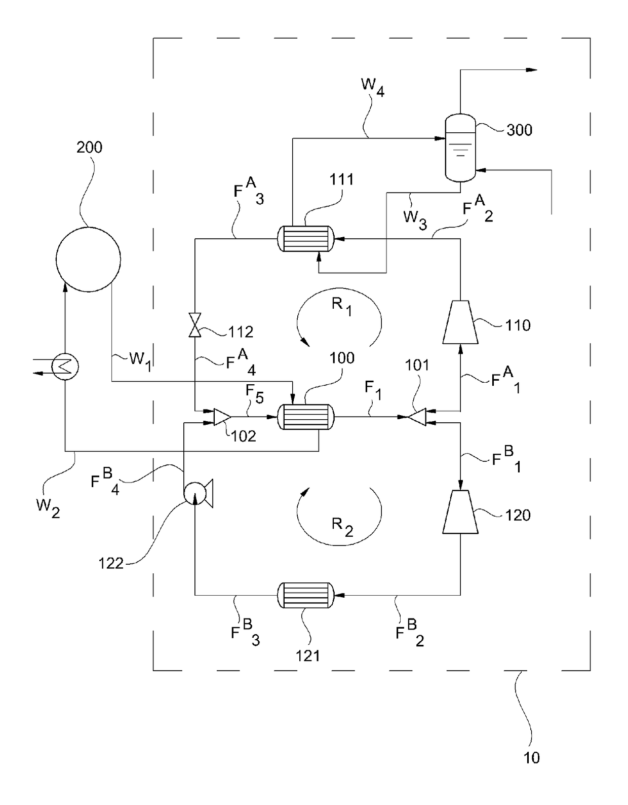
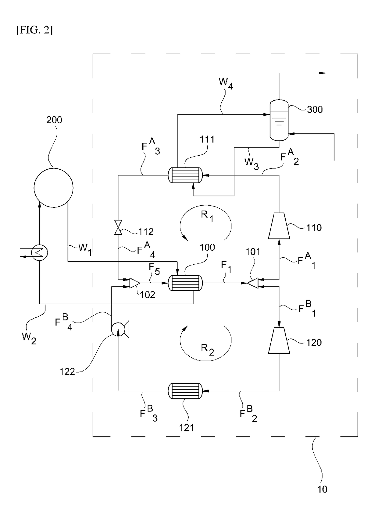
[0126]According to the heat recovery apparatus and method according to the embodiment of the present application, low-level heat sources at a temperature less than 100° C. discharged from industrial settings or various chemical processes, for example, a petrochemicals manufacturing process are not wasted but used to generate steam and the generated steam is used for various processes to reduce an amount of consumed high-temperature steam that is an external heat source to be used for a reactor or distillation column, thereby not only maximizing energy reduction efficiency but also autonomously producing power consumed by a compressor. Also, an evaporation phenomenon of a part of a refrigerant flow which passes through the compressor may be reduced, thereby recovering heat with excellent efficiency.

Problems solved by technology

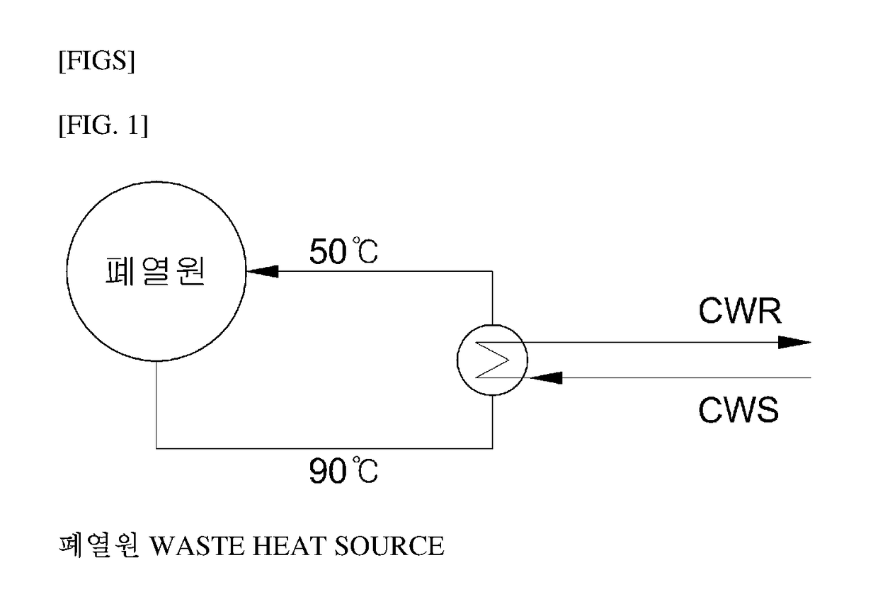
For example, as shown in FIG. 1, when the waste heat is a low-level heat source in a sensible heat state at a temperature of less than 100° C., for example, 50 to 90° C., the waste heat is unable to be substantially reused due to the excessively low temperature thereof, thereby being condensed by condensate water and then wasted.
In this case, to evaporate water in a liquid state, a large amount of energy consumption is necessary.

Method used


Image

  • Heat recovery apparatus
  • Heat recovery apparatus
  • Heat recovery apparatus

Examples


example 1

[0135]Steam was generated using a heat recovery apparatus of FIG. 5.

[0136]A refrigerant 1,1,1,3,3-pentafluoropropane (R245fa) was allowed to flow into an evaporator and to circulate to allow one part of a refrigerant flow separated from the evaporator to sequentially pass through a compressor, a first condenser, and a pressure-dropping device. In detail, a refrigerant flow in a state of 69.6° C., 6.2 kgf / cm2g (7.1 bar), and a gas volume fraction of 0.0 was allowed to flow into the evaporator at a flow rate of 50,000 kg / hr, and simultaneously, a waste heat flow in a state of 85.0° C., 1.0 kgf / cm2g (1.96 bar), and a gas volume fraction of 0.0 was allowed to flow into the evaporator at a flow rate of 300,000 kg / hr to be heat-exchanged. After the heat-exchange, the waste heat flow was discharged in a state of 78.2° C., 1.0 kgf / cm2g (1.96 bar), and a gas volume fraction of 0.0 at a flow rate of 300,000 kg / hr and the refrigerant flow was discharged in a state of 80.0° C., 6.2 kgf / cm2g (7....

example 2

[0140]Steam was generated using a heat recovery apparatus of FIG. 7.

[0141]A refrigerant 1,1,1,3,3-pentafluoropropane (R245fa) was allowed to flow into an evaporator and to circulate to allow one part of a refrigerant flow separated from the evaporator to sequentially pass through a first heat exchanger, a compressor, a first condenser, the first heat exchanger, and a pressure-dropping device. In detail, a refrigerant flow in a state of 69.6° C., 6.2 kgf / cm2g (7.1 bar), and a gas volume fraction of 0.0 was allowed to flow into the evaporator at a flow rate of 50,000 kg / hr, and simultaneously, a waste heat flow in a state of 85.0° C., 1.0 kgf / cm2g (1.96 bar), and a gas volume fraction of 0.0 was allowed to flow into the evaporator at a flow rate of 300,000 kg / hr to be heat-exchanged. After the heat-exchange, the waste heat flow was discharged in a state of 78.2° C., 1.0 kgf / cm2g (1.96 bar), and a gas volume fraction of 0.0 at a flow rate of 300,000 kg / hr and the refrigerant flow was d...

example 3

[0144]A refrigerant flow discharged from an evaporator was allowed to flow into a fluid distributor and separated. After separating the refrigerant flow in the fluid distributor, one part of the refrigerant flow separated in the fluid distributor was allowed to flow into a compressor at a flow rate of 25,000 kg / hr and another part of the refrigerant flow separated in the fluid distributor was allowed to flow into the turbine at a flow rate of 25,000 kg / hr. Also, water which flowed into a first condenser was allowed to flow thereinto at a flow rate of 3,000 kg / hr and the heat-exchanged water was discharged from the first condenser as steam in a state of 115.0° C., 0.7 kgf / cm2g (1.67 bar), and a gas volume fraction of 0.33. Except those described above, the steam was generated through the same method as that of Experimental Example 1.

[0145]A coefficient of performance of the heat recovery apparatus in this case was shown in Table 1.


PUM


Abstract

The present application relates to a heat recovery apparatus and method. According to the heat recovery apparatus and method, low-level heat sources at a temperature less than 100° C. discharged from industrial settings or various chemical processes, for example, a petrochemicals manufacturing process are not wasted but used to generate steam and the generated steam is used for various processes to reduce an amount of consumed high-temperature steam that is an external heat source to be used for a reactor or distillation column, thereby not only maximizing energy reduction efficiency but also autonomously producing power consumed by a compressor. Also, an evaporation phenomenon of a part of a refrigerant flow which passes through the compressor may be reduced, thereby recovering heat with excellent efficiency.

Description

TECHNICAL FIELD[0001]The present application relates to a heat recovery apparatus and method.BACKGROUND ART[0002]In general chemical processes, heat exchange is performed in various routes which pass through reactors or distillation columns and waste heat generated after heat exchange may be reused or wasted. For example, as shown in FIG. 1, when the waste heat is a low-level heat source in a sensible heat state at a temperature of less than 100° C., for example, 50 to 90° C., the waste heat is unable to be substantially reused due to the excessively low temperature thereof, thereby being condensed by condensate water and then wasted.[0003]Meanwhile, low pressure or high pressure steam is variously used. Particularly, high temperature and high pressure steam is generally used in chemical processes. Generally, atmospheric pressure and room temperature water is heated to the evaporation point and high pressure is applied to the water converted into steam to increase internal energy, t...

Claims


Application Information

Patent Timeline
Patent Type & Authority Applications(United States)
IPC IPC(8): F25B6/02F01K13/02F01K11/02F01K25/08F25B11/04F01K7/16
CPCF25B6/02F25B11/04F01K7/16F25B2339/047F01K25/08F01K13/02F25B2500/19F01K11/02Y02P20/10Y02P80/15Y02P80/10F02C6/18F25J2240/82F25J2240/70
Inventor KIM, TAE WOOLEE, SUNG KYUSHIN, JOON HO
Owner LG CHEM LTD
Why Eureka
Try Eureka