Exhaust heat recovery device and binary electricity generation device

a heat recovery device and heat recovery technology, applied in the direction of greenhouse gas reduction, steam generation using hot heat carriers, lighting and heating apparatus, etc., can solve the problems of excessive corrosive components may condense from low-temperature exhaust gas, and corrode pipes, so as to achieve efficient heat recovery of exhaust gas

Active Publication Date: 2019-08-29
KOBE STEEL LTD
View PDF2 Cites 6 Cited by
  • Summary
  • Abstract
  • Description
  • Claims
  • Application Information

AI Technical Summary

Benefits of technology

[0005]It is an object of the present invention to efficiently recover heat from an exhaust gas containing a corrosive component.

Problems solved by technology

In this case, in an attempt to recover heat from an exhaust gas containing a corrosive component such as sulfur, there is a fear that a corrosive component may condense from a low-temperature exhaust gas from which heat is recovered, to corrode a pipe and the like.
For this reason, it is unable to excessively recover heat of an exhaust gas, and thus, there arises a problem of inability to efficiently generate electricity.

Method used


Image

  • Exhaust heat recovery device and binary electricity generation device
  • Exhaust heat recovery device and binary electricity generation device
  • Exhaust heat recovery device and binary electricity generation device

Examples


Embodiment Construction

[0015]Hereinafter, embodiments for carrying out the present invention will be described in detail with reference to the drawings.

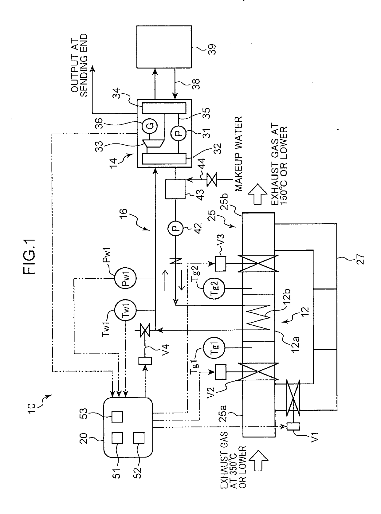
[0016]As shown in FIG. 1, an exhaust heat recovery device 10 according to the present embodiment is a device for recovering exhaust heat from a gas which is used as a heat-source gas of a boiler 12, and includes the boiler 12, a binary electricity generation device 14, a heat medium circuit 16, and a controller 20. The boiler 12 and the binary electricity generation device 14 are connected with each other via the heat medium circuit 16.

[0017]The boiler 12 is connected with a main passage 25 though which an exhaust gas serving as a heat-source gas flows. The main passage 25 includes an upstream portion 25a and a downstream portion 25b which are located on an upstream side and a downstream side, respectively, with the boiler 12 connected with the heat medium circuit 16 being interposed therebetween. The boiler 12 has a configuration in which a pipe 12b is ho...


PUM


Abstract

An exhaust heat recovery device includes: a main passage through which an exhaust gas containing a corrosive component flows; a boiler which heats a heat medium using the exhaust gas; a bypass passage connected to the main passage so as to detour around the boiler; a regulation valve member which regulates a flow rate of the exhaust gas flowing into the boiler; a heat medium circuit which circulates the heat medium that is heated to be in a hot-water state by the boiler; a binary electricity generation device which recovers thermal energy from the heat medium in the heat medium circuit and generates electricity; and a valve control unit which controls an opening of the regulation valve member such that a temperature of the exhaust gas passed through the boiler is equal to or higher than a temperature of an acid dew-point of the corrosive component in the exhaust gas.

Description

TECHNICAL FIELD[0001]The present invention relates to an exhaust heat recovery device and a binary electricity generation device.BACKGROUND ART[0002]Conventionally, as disclosed in the following Patent Literature 1, for example, an exhaust heat recovery device including a binary electricity generation device is known. In an exhaust heat recovery device disclosed in the following Patent Literature 1, it is designed such that a working medium is evaporated in an evaporator of a binary electricity generation device, using heat of cooling water of an engine, and a power turbine is driven by the evaporated working medium, to generate electricity.[0003]In the above-described exhaust heat recovery device disclosed in Patent Literature 1, cooling water of an engine is used as a heat source for evaporating a working medium of the binary electricity generation device. In the meantime, it is conceivable to use heat of an exhaust gas as a heat source. In this case, in an attempt to recover heat...

Claims


Application Information

Patent Timeline
Patent Type & Authority Applications(United States)
IPC IPC(8): F22B1/18F01N5/02
CPCF01N5/02F22B1/1807F01K23/10F01K25/10F02G5/02Y02E20/30Y02P80/15Y02T10/12F01K23/101F22B1/18F01K13/02
Inventor TAKAHASHI, KAZUO
Owner KOBE STEEL LTD
Why Eureka
Try Eureka