Integrated Pumper Apparatus

a pumper and integrated technology, applied in the field of firefighting equipment for pumpers, can solve the problem of very costly and time-consuming emergency response efforts

Active Publication Date: 2011-10-27
SPARTAN FIRE LLC
View PDF2 Cites 9 Cited by
  • Summary
  • Abstract
  • Description
  • Claims
  • Application Information

AI Technical Summary

Problems solved by technology

However, this can make responding to emergencies a very costly endeavor, especially for communities with small populations or limited resources.

Method used


Image

  • Integrated Pumper Apparatus
  • Integrated Pumper Apparatus
  • Integrated Pumper Apparatus

Examples


Embodiment Construction

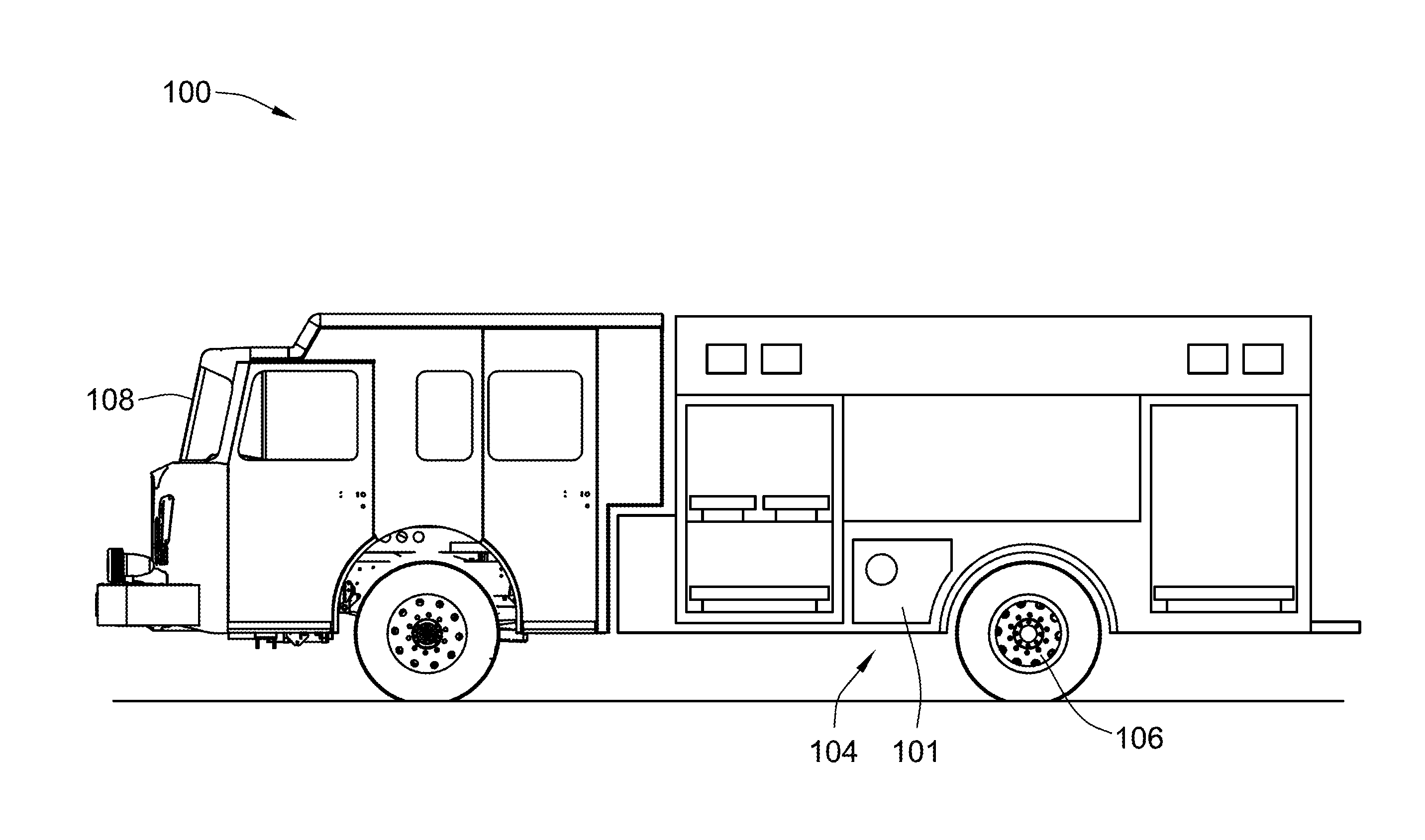
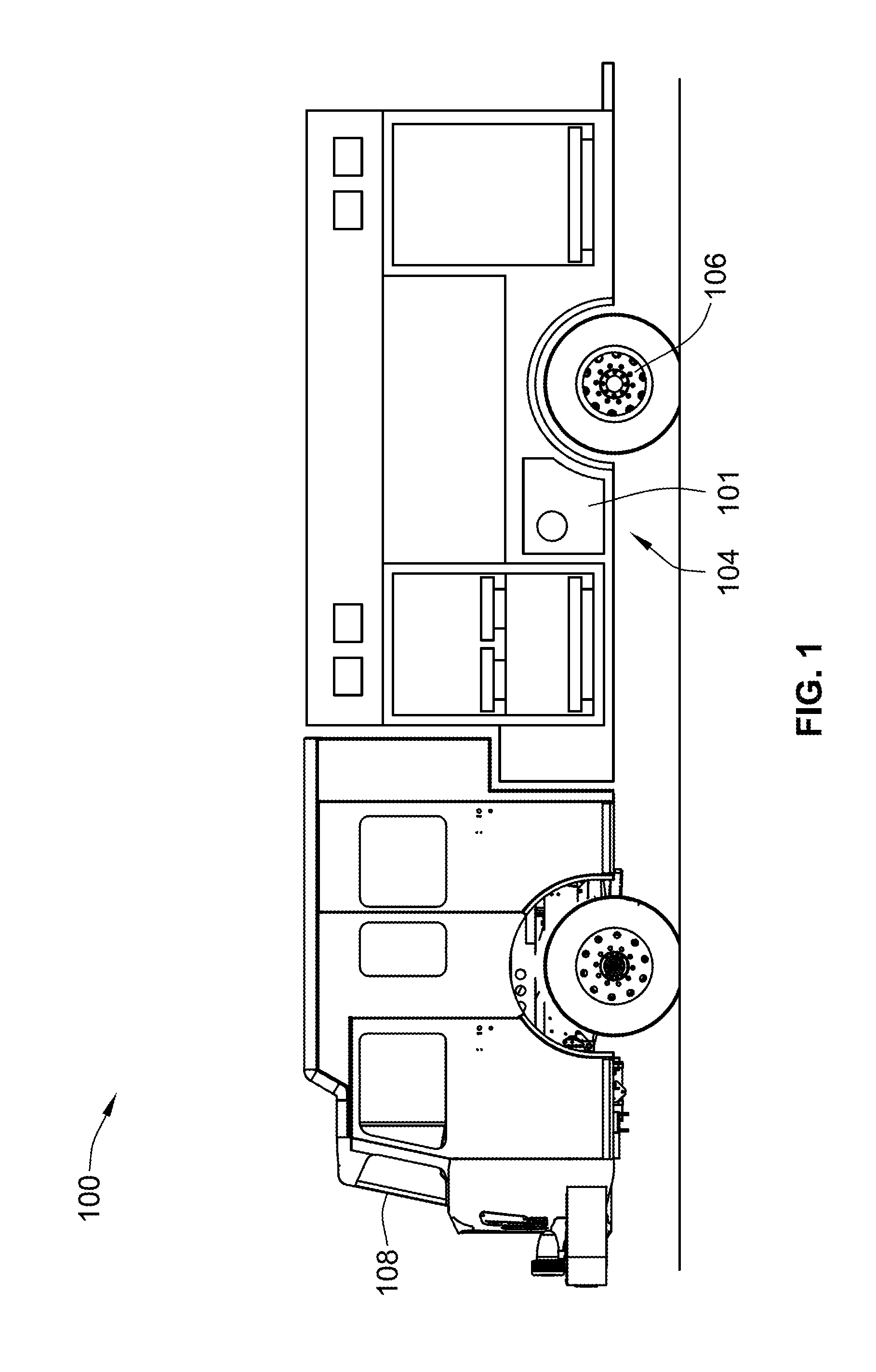
[0018]Embodiments of the invention are described primarily in terms of its use on what has historically been termed a Class A pumper. Such a pumper is designed to meet the requirements set forth in NFPA 1901. Among the many requirements of NFPA 1901 is a requirement that the pumper have one or more water tanks with a total capacity of at least 300 gallons, and includes a fire pump with a minimum rated capacity of 750 gallons per minute (gpm). Further, for any pump rated at equal to or less than 2500 gpm, the pump must be able to supply 100% or rated pump capacity at 150 psi, 70% of rated capacity at 200 psi, and 50% of rated capacity at 250 psi. It is contemplated that embodiments of this invention includes a pumper vehicle with a fire pump having a rated capacity of up to approximately 1500 gpm, but is not limited to such.

[0019]Additionally, under NFPA 1901, pumpers are required to have a minimum of 40 cubic feet of storage for tools and equipment, and a minimum hose storage area o...


PUM


Abstract

A fire-fighting pumper vehicle that includes a cab configured to transport a crew of firefighters, a water tank disposed to the rear of the cab, and a chassis configured to support the cab, the water tank, and one or more fire pump systems disposed on the chassis proximate to, and forward of, the rear wheels. In some embodiments, the fire pump system includes a power take-off pump, which is configured to operate a water only system or a compressed-air foam system from a gear case of the fire pump. The fire pump system includes nested components and is located and configured to occupy less space than conventional fire pump systems.

Description

CROSS-REFERENCE TO RELATED PATENT APPLICATIONS[0001]This patent application claims the benefit of U.S. Provisional Patent Application No. 61 / 326,262, filed Apr. 21, 2010, the entire teachings and disclosure of which are incorporated herein by reference thereto.FIELD OF THE INVENTION[0002]This invention generally relates to fire-fighting equipment, and more particularly to fire-fighting equipment for a pumper vehicle.BACKGROUND OF THE INVENTION[0003]Traditionally, it has been the case in the fire-fighting industry that, for each type of emergency event, a specific vehicle has been designed that is adapted to respond to, and support fire-fighters in responding to, that type of emergency event. For example, when a structure catches on fire, the fire department would traditionally require a strictly pumper-style fire-fighting vehicle, while a car accident would require a different rescue-style vehicle.[0004]In each case, custom, or tradition, has driven the need for multiple specialized...

Claims


Application Information

Patent Timeline
Patent Type & Authority Applications(United States)
IPC IPC(8): A62C27/00
CPCA62C27/00
Inventor VER STEEG, DAVID A.CRESSMAN, PAUL D.
Owner SPARTAN FIRE LLC
Why Eureka
Try Eureka