A kind of compressed air foam side spray release device and using method

A technology of compressed air foam and foam, which is applied in fire rescue and other fields, can solve the problems that cannot meet the actual application requirements of side spray nozzles, is not suitable for installation and use on side walls, and affects the normal entry and exit of cars, etc., and achieves simple structure, large protection range, The effect of high foaming ratio

Active Publication Date: 2019-01-18
应急管理部天津消防研究所
View PDF6 Cites 0 Cited by
  • Summary
  • Abstract
  • Description
  • Claims
  • Application Information

AI Technical Summary

Problems solved by technology

[0004] However, the existing compressed air foam nozzles are mainly drooping nozzles, which cannot meet the actual application requirements of side spray nozzles in road tunnels, three-dimensional garages and other places.
For example, U.S. Patent US6328225 discloses a compressed air foam rotary nozzle, and Chinese patent CN201410707575.7 discloses a compressed air foam spraying method and nozzles. Under building ceilings, not suitable for side wall installation
Especially when it is used in special spaces such as three-dimensional shelves and garages, due to the occlusion of such places, when a fire occurs at the bottom or bottom, it is difficult for the foam to cover the fire source. If the layered arrangement is adopted, one is Due to the limitation of each partition space, there is a lack of space for arranging nozzles. Second, it affects the normal entry and exit of cars, goods, etc., and it is easy to cause collisions and damage the nozzles.

Method used


Image

  • A kind of compressed air foam side spray release device and using method
  • A kind of compressed air foam side spray release device and using method
  • A kind of compressed air foam side spray release device and using method

Examples


Embodiment 1

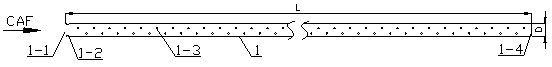
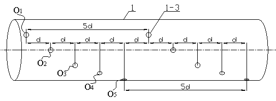
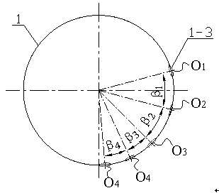
[0020] Such as figure 1 , 2 , 3, 4, and 7, the foam branch pipe 2 communicates with two release pipes 1 through the connection tee 3, wherein the release pipe 1 is made of galvanized steel pipe, the diameter D of the release pipe is 100mm, and the length L is 6m. Five rows of release holes 1-3 are evenly distributed on one side surface of 1 according to a certain distance and angle, and the number of release holes 1-3 from top to bottom is o 1 , o 2 ...o 5 , the hole diameters of each row of discharge holes 1-3 are 8mm, 8mm, 8mm, 6mm, and 6mm from top to bottom, and the horizontal distance between two adjacent discharge holes is 50mm. The distance d between the discharge holes is 250mm, and the angles between each row of release holes are 30°, 30°, 20°, and 20° from top to bottom, among which, according to the formula The foam inlet cross-sectional area A of the release pipe 1 can be calculated 1 0.00785 m 2 , according to the formula The total cross-sectional area A ...

Embodiment 2

[0030] Example 2 as Figure 5 , 6 , 7, the release pipe 1 communicates with the foam branch pipe 2 through the connection tee 3, wherein the release pipe 1 is made of galvanized steel pipe and is arc-shaped, the diameter D of the release pipe is 100mm, and the length L is 10m. Six rows of discharge holes 1-3 are evenly distributed on the surface according to a certain distance and angle, and the discharge holes 1-3 are numbered from top to bottom as o 1 , o 2 ...o 6, the diameter of each row of discharge holes 1-3 is 8mm, the horizontal distance between two adjacent discharge holes is 70mm, the distance d between two adjacent holes in each row of discharge holes is 420mm, and the release holes in each row are evenly arranged On the surface of the discharge pipe, the angles between the rows of discharge holes are 35°, 40°, 40°, 40°, and 35° from left to right, that is, the 190° arc surface of the discharge pipe is covered. In this embodiment The compressed air foam side spr...


PUM


Abstract

The invention relates to a compressed air foam side spraying and discharging device and a using method. Each discharging pipe is a straight pipe with one end being a closed end, the other end being open as a compressed air foam inlet, the pipe length L being 2 m to 20 m and the diameter D being 20 mm to 200 mm or a bent pipe with a certain radian; a plurality of rows of discharging holes with the distance d being 20 mm to 100 mm are evenly distributed in the surface of each discharging pipe; the hole diameter of the discharging holes is 1 mm to 30 mm; the included angle beta between the discharging holes ranges from 10 degrees to 35 degrees; the ratio of the area Al of the cross section of the foam inlet of each discharging pipe to the total area A2 of the cross sections of the corresponding discharging holes should meet the formula (please see the formula in the description); a foam branch pipe communicates with the two discharging pipes through connection pieces; and once a fire happens, a compressed air foam system provides compressed air foam for the discharging pipes according to set characteristic pressure, then the compressed air foam is evenly sprayed to a fire protection area through the discharging holes in different positions, and the beneficial effects that the device is simple in structure, safe and reliable, uniform in foam spraying, wide in protection range, convenient to install and use, high in foaming expansion rate, long in drainage time, high in stability and high in fire extinguishing efficiency are achieved.

Description

technical field [0001] The invention belongs to a compressed air foam dispensing device, in particular to a compressed air foam side spray dispensing device and a use method. Background technique [0002] Fixed compressed air foam fire extinguishing technology is a new type of foam fire extinguishing technology gradually developed in recent years. It generates foam by injecting air into the foam solution under positive pressure. The compressed air foam has a fine and uniform structure, long liquid separation time and high stability, and can cover the surface of the protected object for a long time. Compared with the existing water-based fire extinguishing technologies such as water spray and foam-water spray, compressed air foam has the following outstanding advantages: 1) It has high fire extinguishing efficiency for Class A fires and Class B fires, and the water consumption is small, and it will not Water damage occurs; 2) The foam performance is stable, with good "accumu...

Claims


Application Information

Patent Timeline
Patent Type & Authority Patents(China)
IPC IPC(8): A62C5/02A62C31/12
CPCA62C5/024A62C31/12
Inventor 傅学成宋波陈涛胡成包志明王荣基
Owner 应急管理部天津消防研究所
Why Eureka
Try Eureka