Eureka AIR delivers breakthrough ideas for toughest innovation challenges, trusted by R&D personnel around the world.

Compressed air foam plug box system and fire extinguishing method for tunnel rescue station

A compressed air foam and rescue station technology, applied in fire rescue and other directions, can solve the problems that the actual application requirements of tunnel rescue stations cannot be met, the deluge system is not suitable for tunnel rescue stations, and foam is difficult to apply, so as to ensure the high efficiency of fire extinguishing, Guaranteed safety and reliability, easy to control the effect

Active Publication Date: 2019-01-22
应急管理部天津消防研究所
View PDF6 Cites 0 Cited by
  • Summary
  • Abstract
  • Description
  • Claims
  • Application Information

AI Technical Summary

Problems solved by technology

This deluge system is an automatic fire extinguishing system. Since the train fire mainly occurs inside the carriage, and the metal body of the train blocks the foam, it is difficult to apply the foam to the interior of the carriage. Therefore, the existing deluge system is not suitable for tunnel rescue stations.
In addition, existing compressed air foam fire trucks can use compressed air foam guns or cannons and manually release compressed air foam. However, this system is a mobile fire extinguishing equipment with a complex structure and requires professional firefighters to operate, which cannot meet the needs of tunnel rescue stations. practical application needs

Method used


Image

  • Compressed air foam plug box system and fire extinguishing method for tunnel rescue station
  • Compressed air foam plug box system and fire extinguishing method for tunnel rescue station
  • Compressed air foam plug box system and fire extinguishing method for tunnel rescue station

Examples


Embodiment Construction

[0022] Further illustrate the present invention below in conjunction with embodiment and accompanying drawing.

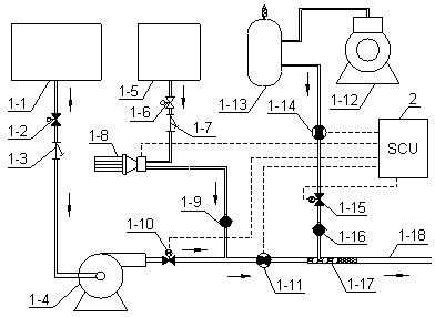
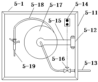
[0023] Such as figure 1 As shown, a compressed air foam lock box system for a tunnel rescue station includes a compressed air foam generator 1 , a system controller 2 , and a compressed air foam lock box 5 .

[0024] The compressed air foam generating device 1 and the system controller 2 are arranged in the equipment chamber of the tunnel 6 rescue station, and several compressed air foam plug boxes 5 are respectively arranged on the two side walls of the tunnel 6 rescue station, and several compressed air foam plug boxes The box 5 is connected with the compressed air foam generator 1 respectively through the foam pipeline 3, and several compressed air foam plug boxes 5 are connected with the system controller 2 through the signal control line 4 respectively, and the compressed air foam generator 1 is connected with the system controller 2 through the signal control ...


PUM


Abstract

The invention relates to a compressed air foam hydrant system of a tunnel rescue station and a fire extinguishing method. When a fire happens at the tunnel rescue station, field operators open one or more compressed air foam hydrants and press a start button; a system controller starts a compressed air foam generating device, a sectional control valve is started, the water flow is adjusted automatically according to the number of signals fed by alarm control units, and the foam fluid and air flow are also automatically adjusted according to the water flow, so that compressed air form is formed; the field operators hold foam guns with hands to align at the ignition area of a train so as to jet the compressed air foam, so that targeted fire extinguishing is achieved; and after the fire is extinguished, the system recovers to the initial state of the normal condition. Through the mode that the dual foam gun compressed air foam hydrants are adopted, the situation that the whole hydrant system fails when one set of hydrant breaks down is avoided, the safety and reliability of the system are ensured, the foam flow of each single foam gun can be reduced, and accordingly the foam guns are easier to control. The safety, reliability and high fire extinguishing efficiency of the system are ensured.

Description

technical field [0001] The invention belongs to fire-fighting fixed fire-extinguishing facilities, in particular to a compressed air foam plug box system and a fire-extinguishing method of a tunnel rescue station. Background technique [0002] With the rapid development of railway construction, there are more and more long railway tunnels. While these long railway tunnels bring convenience to transportation, they also put forward higher requirements for tunnel disaster prevention and rescue. Especially for ultra-long tunnels with a length of more than 20km, once a train fire accident occurs in the tunnel, it is difficult to drive out of the tunnel only relying on residual power, so a rescue station must be set up in the tunnel to evacuate the train personnel to the safe area of ​​the rescue station Carry out risk avoidance, and use the fire fighting facilities of the rescue station to timely extinguish the train fire. Therefore, it is of great significance to set up reliab...

Claims


Application Information

Patent Timeline
Patent Type & Authority Patents(China)
IPC IPC(8): A62C3/02A62C5/02A62C31/00A62C37/36
CPCA62C3/0221A62C5/02A62C31/00A62C37/36
Inventor 韩伟平陈涛宋波胡成夏建军包志明张宪忠陈旸
Owner 应急管理部天津消防研究所
Why Eureka
Eureka Blog
Learn More