Receiving apparatus, image-forming apparatus, receiving method and recording medium

a technology of image-forming apparatus and receiving apparatus, which is applied in the direction of digital output to print units, instruments, computing, etc., can solve the problems of non-established communication, failure to establish communication with the sender, and the image-reading apparatus of patent document 1 is not capable of solving such a problem, so as to prevent a failure in establishing communication and obtain emi-reducing effects

Active Publication Date: 2011-10-27
SHARP KK
View PDF2 Cites 1 Cited by
  • Summary
  • Abstract
  • Description
  • Claims
  • Application Information

AI Technical Summary

Benefits of technology

[0021]The present invention has been made with the aim of solving the above problem, and it is an object of the present invention to provide a receiving apparatus and an image-forming apparatus which, when receiving data including a plurality of bits based on a spread clock signal, is capable of adjusting the change cycle of the spread clock signal according to the receiving time per bit, and thereby capable of preventing a failure in establishing communication when receiving data using the spread clock signal, and certainly obtaining EMI reducing effects.

Problems solved by technology

In such a case, however, using the spread clock signal for performing serial communication sometimes causes a problem of non-established communication.
Therefore, the receiver performs data sampling of data bit (D7) at the timing of data sampling the stop bit, and fails to establish communication with the sender.
However, the image-reading apparatus of Patent Document 1 is not capable of solving such a problem.

Method used


Image

  • Receiving apparatus, image-forming apparatus, receiving method and recording medium
  • Receiving apparatus, image-forming apparatus, receiving method and recording medium
  • Receiving apparatus, image-forming apparatus, receiving method and recording medium

Examples


embodiment 1

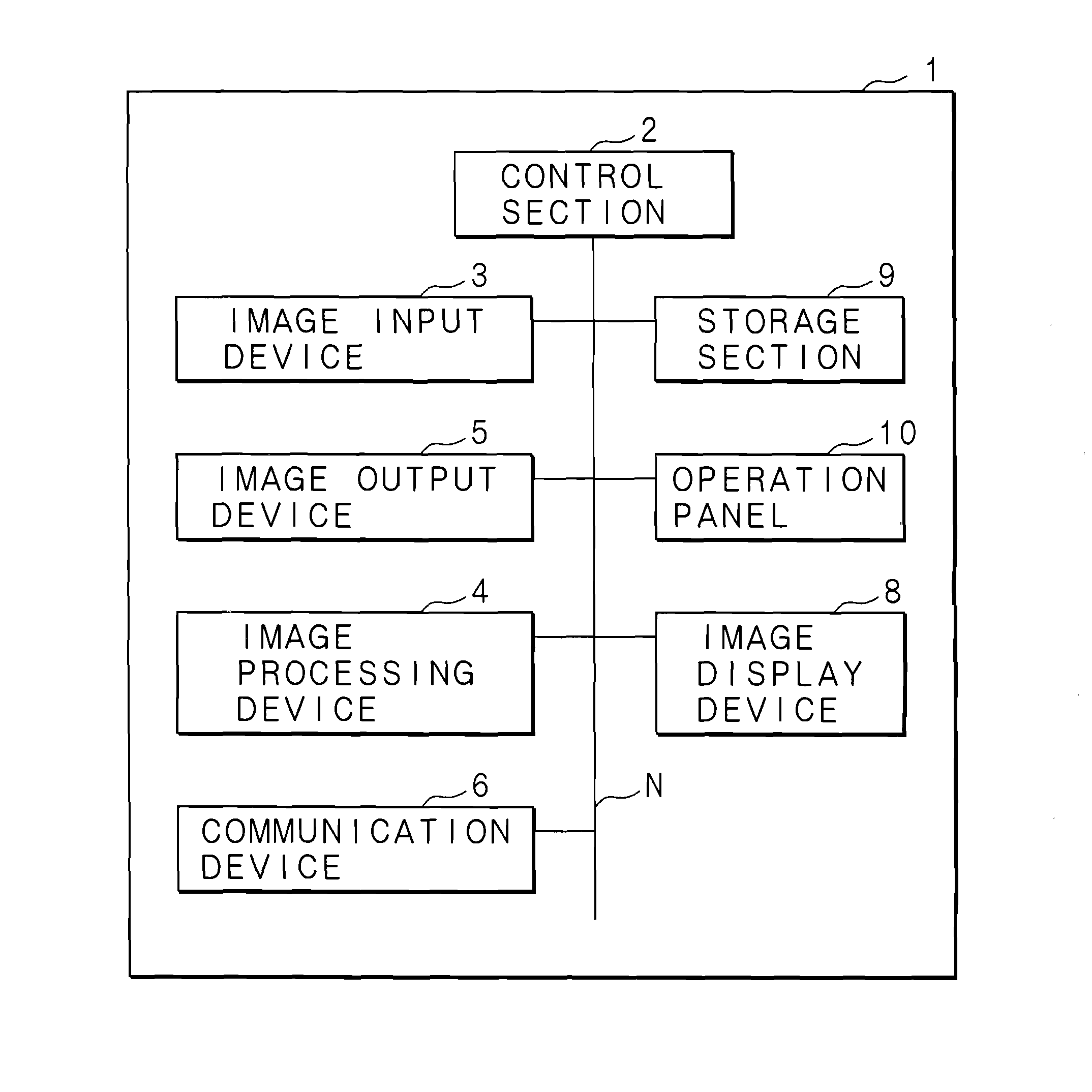
[0045]FIG. 5 is a functional block diagram for explaining the essential configuration of a multi-function printer according to Embodiment 1 of the Present Invention.

[0046]The multi-function printer 1 of Embodiment 1 of the present invention comprises: an image input device 3; an image output device 5; an image processing device 4; a communication device 6; an image display device 8; a storage section 9 (storage means); and an operation panel 10. These hardware devices are connected to a control section 2 by a bus N.

[0047]The image input device 3 comprises: a light source for irradiating light on a document to be read; and an image sensor such as a CCD (Charge Coupled Device), and optically reads an image on the document. In the image input device 3, a reflected light image from the document set on a given read place is focused onto the image sensor, and RGB (R: Red, G: Green, B: Blue) analog data are outputted.

[0048]The image output device 5 prints an image based on image data outpu...

embodiment 2

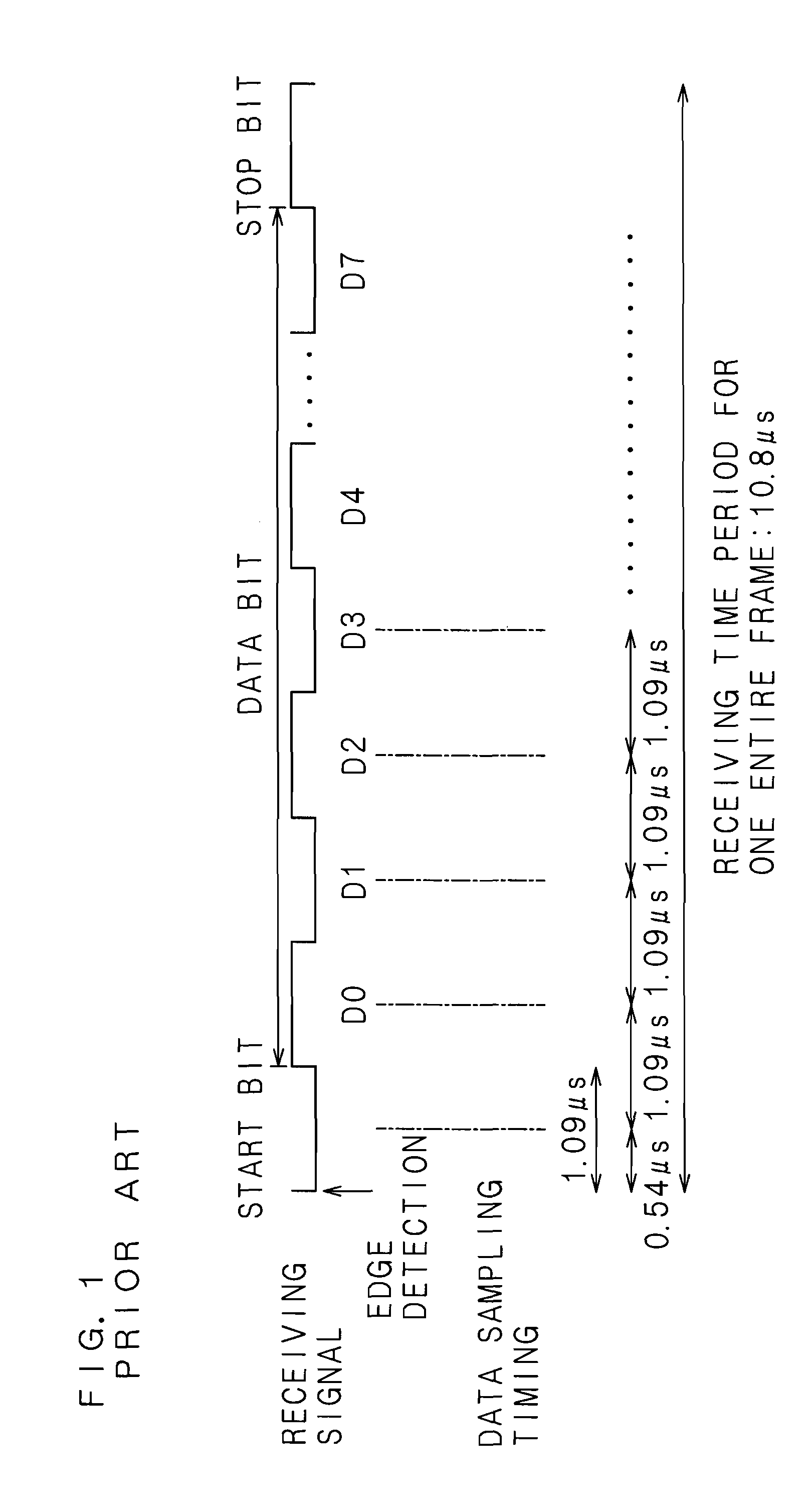
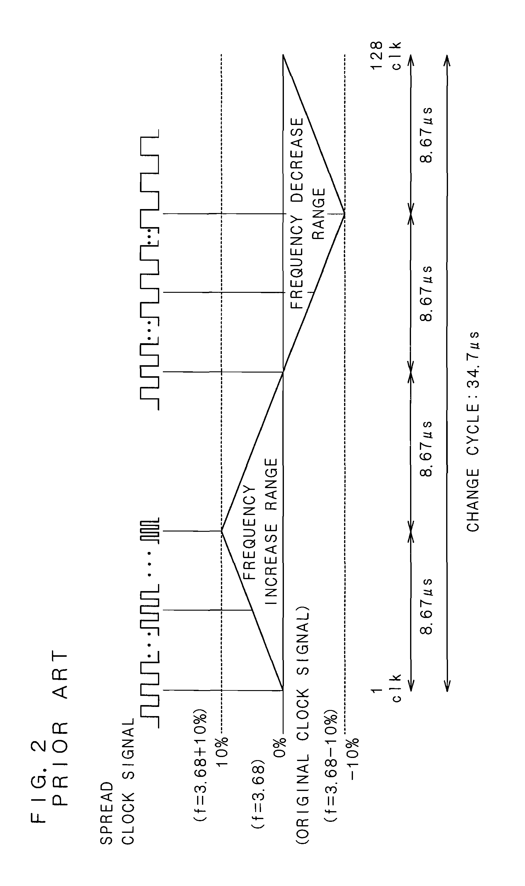
[0078]A multi-function printer 1 according to Embodiment 2 of the present invention has substantially the same configuration as that of the multi-function printer 1 of Embodiment 1, but this invention is different in the function of the modulating section 125 of the clock-spreading device 12. For the sake of simplifying the explanation, like Embodiment 1, Embodiment 2 is explained by way of an example in which start-stop synchronous communication is performed between the image input device 3 and the image output device 5, and the image input device 3 receives data sent frame by frame from the image output device 5 by using a spread clock signal. Note that the frame has M bits.

[0079]When receiving data sent frame by frame from the engine control section 52 of the image output device 5, the read control section 32 of the image input device 3 detects an edge of the start bit, and receives the data in synchronization with a spread clock signal from the clock-spreading device 12.

[0080]In...


PUM


Abstract

When receiving data in a unit of frame, each frame including a plurality of bits, based on a spread clock signal, a receiving time per bit of receiving data is calculated based on a receiving rate, and the change cycle of the spread clock signal is adjusted according to the receiving time per bit.

Description

CROSS-REFERENCE TO RELATED APPLICATION[0001]This non-provisional application claims priority under 35 U.S.C. §119(a) on Patent Application No. 2010-102425 filed in Japan on Apr. 27, 2010, the entire contents of which are hereby incorporated by reference.BACKGROUND[0002]1. Technical Field[0003]The present invention relates to a receiving apparatus having a clock generating section for outputting a spread clock signal which is generated by cyclically increasing and decreasing the frequency of a clock signal, to an image-forming apparatus comprising the receiving apparatus, to receiving method and to recording medium.[0004]2. Description of Related Art[0005]Conventional circuits for preventing EMI (Electro Magnetic Interference) of electronic equipment use methods, such as a method of filtering harmonic components of a clock signal of the electronic equipment, a method of effectively securing a return ground (GND), and a method of scattering radiation energy by spreading the spectrum o...

Claims


Application Information

Patent Timeline
Patent Type & Authority Applications(United States)
IPC IPC(8): H04B1/707G06F3/12
CPCH04N1/00222
Inventor NISHIO, YUKIHITO
Owner SHARP KK
Why Eureka
Try Eureka