Intraocular Lens Insertion Device

Active Publication Date: 2011-10-27
HOYA CORP
View PDF5 Cites 63 Cited by
  • Summary
  • Abstract
  • Description
  • Claims
  • Application Information

AI Technical Summary

Benefits of technology

[0015]According to the intraocular lens insertion device of the present invention, the stop means causes the lens contact portion to be temporarily stopped as the intraocular lens passes thorough the vicinity of the distal end portion of the insertion tube, thus allowing the lens contact portion to be stopped before the intraocular lens is released even when a large external force against a r

Problems solved by technology

However, the intraocular lens needs to be moved forward while balancing the friction resistance between the intraocular lens and the inner wall of the insertion tube with the pressure applied to the operation portion, thus making it relatively difficult to control the pressure applied to the operation portion.
Therefore, there is a possibility tha

Method used


Image

  • Intraocular Lens Insertion Device
  • Intraocular Lens Insertion Device
  • Intraocular Lens Insertion Device

Examples


first embodiment

1. First Embodiment

[0042](1) Overall Structure

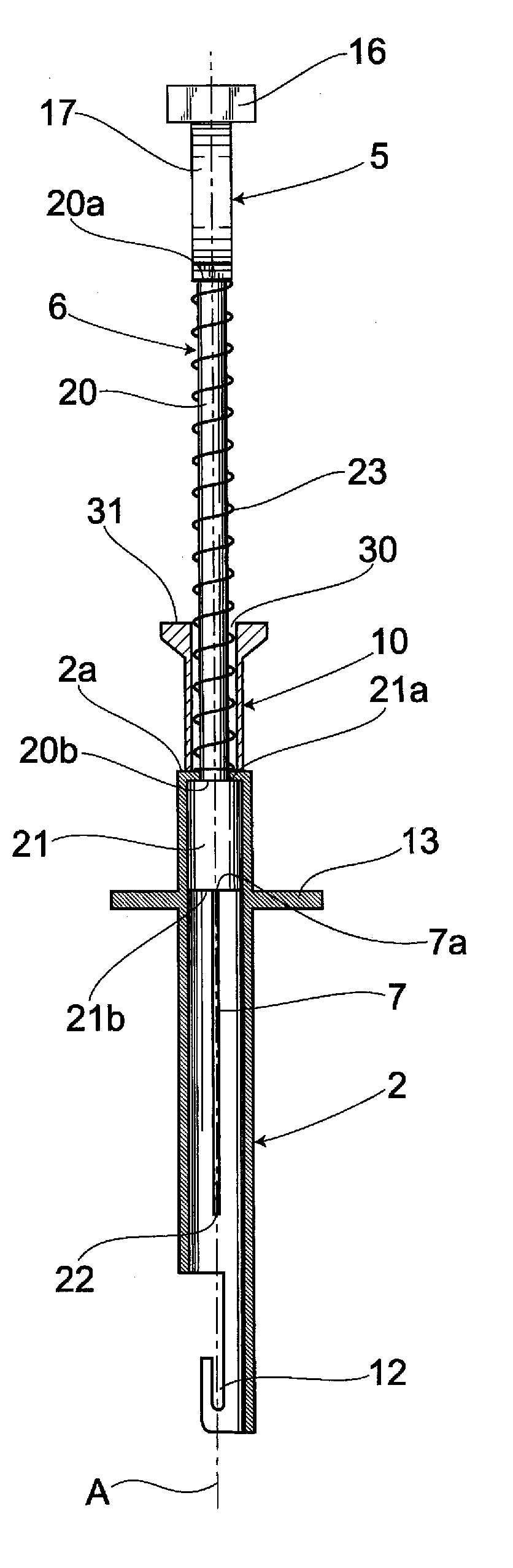
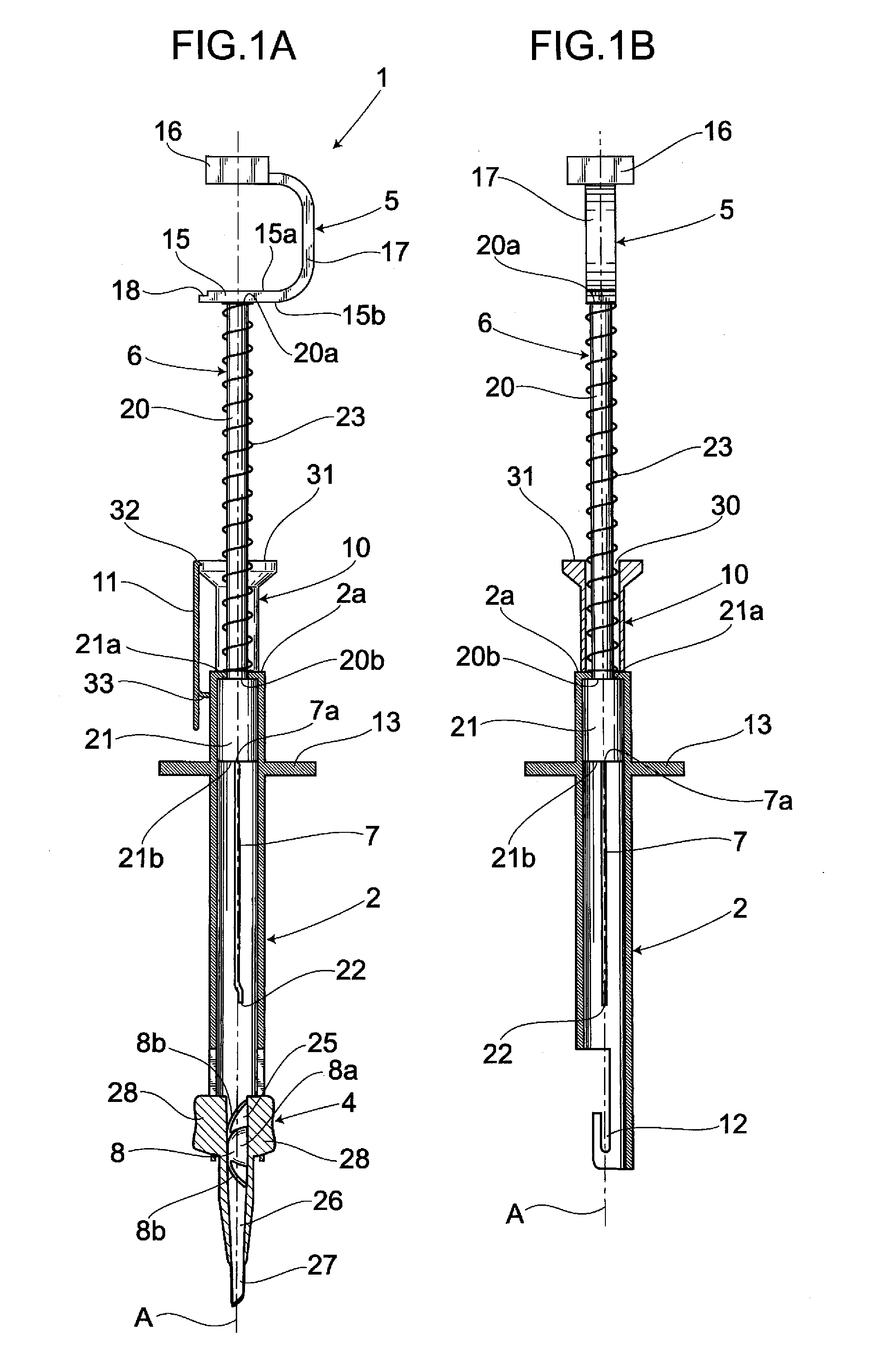
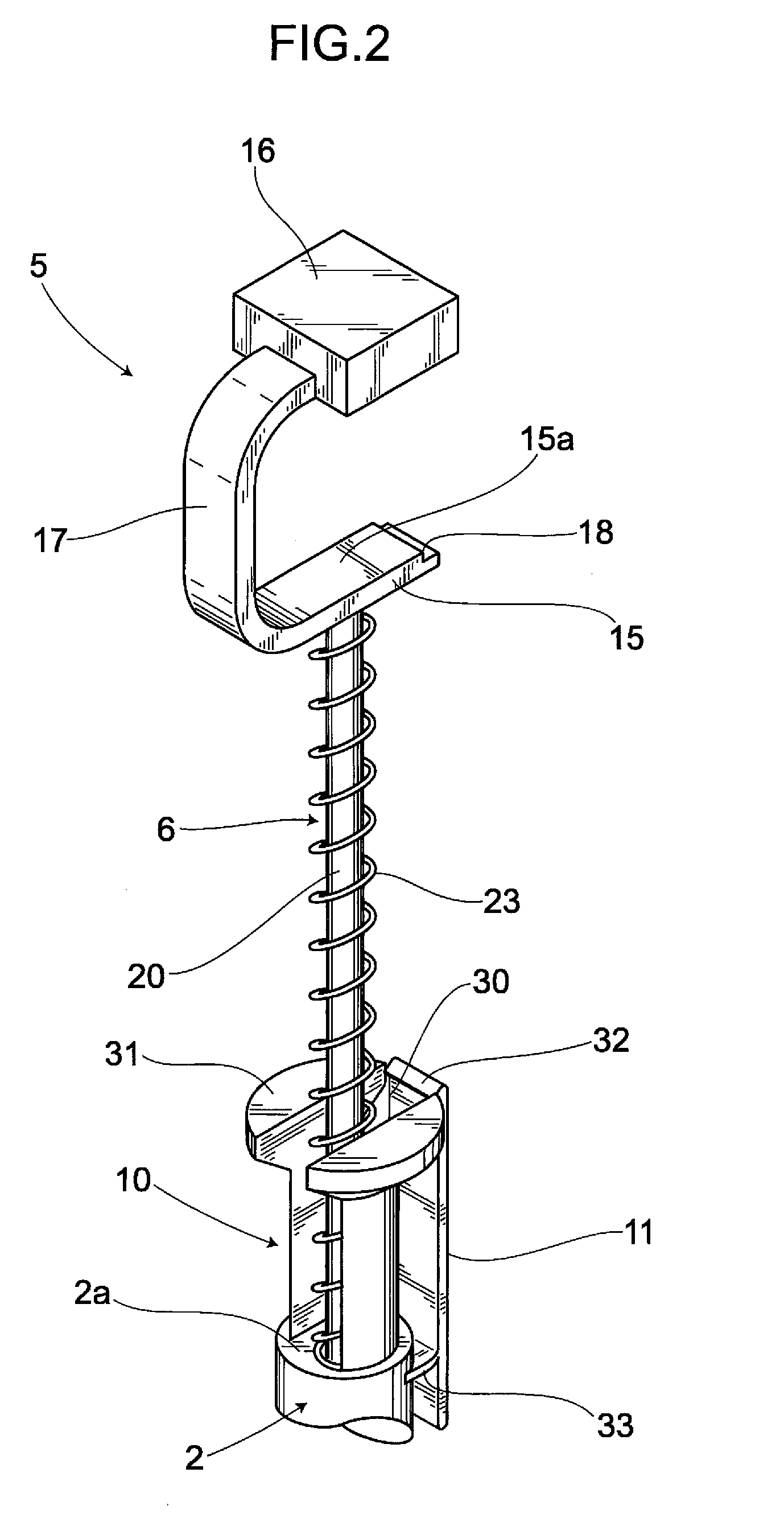
[0043]An intraocular lens insertion device 1 shown in FIG. 1 comprises a main body 2, a cartridge 4 attached to the main body 2 and an operation portion 5. A plunger 6 serving as a transmitting portion is connected to the operation portion 5. A rod 7 for pushing out an intraocular lens 8 is provided on a distal end of the plunger 6. The operation portion 5 is located away from one end 2a of the main body 2. In this sense, the intraocular lens 8 placed in the cartridge 4 can be pushed out by the rod 7 as a whole as an operator pushes the operation portion 5. Here, a type of disposable insertion tube that allows the operator or an assistant to place the intraocular lens 8 thereinside at the time of operation is generally called a cartridge.

[0044]In addition to the aforementioned structure, the intraocular lens insertion device 1 of the present embodiment comprises a stop means described later. Such stop means allows the rod 7 to first push...

second embodiment

2. Second Embodiment

[0069](1) Overall Structure

[0070]According to the aforementioned first embodiment, the lens contact portion is stopped temporarily as the operator's finger pushing the operation portion has come to abut against the stop means. The present embodiment differs from the first embodiment in that a lens contact portion is mechanically stopped temporarily by allowing an operation portion to abut against a stop means. Same reference numbers are used to describe the same parts as those in the aforementioned embodiment, thus omitting the descriptions of such parts for the sake of simplicity.

[0071]An intraocular lens insertion device 41 shown in FIG. 7 comprises a main body 42 and an operation portion 43. An insertion tube portion 44 in which an intraocular lens 8 has been placed in advance is attached to the main body 42. In general, the intraocular lens insertion device 41 is a preload type intraocular lens insertion device fixed in a case not shown and packaged as well a...

third embodiment

3. Third Embodiment

[0092](1) Overall Structure

[0093]An intraocular lens insertion device of the present embodiment differs from the aforementioned first embodiment in that it comprises a knock mechanism. Here, same reference numbers are used to describe the same parts as those in the aforementioned embodiments, thus omitting the descriptions of such parts for the sake of simplicity.

[0094]An intraocular lens insertion device 61 shown in FIG. 11 comprises a main body 62, an operation portion 63, a knock mechanism 64 allowing the operation portion 63 to move to the forward and backward directions with respect to the main body 62 and a cartridge 65 attached to an other end 62b of the main body 62. Overall, the knock mechanism 64 repeatedly causes the operation portion 63 to move to the forward and backward directions, thereby allowing an intraocular lens 8 placed in the cartridge 65 to be pushed out in a step-wise manner.

[0095]The knock mechanism 64 is capable of pushing the intraocular...


PUM


Abstract

There is provided an intraocular lens insertion device capable of more easily inserting an intraocular lens into an eye. An intraocular lens insertion device 1 comprises a main body 2, an operation portion 5 and a cartridge 4 attached to the main body 2. The operation portion 5 has a plunger 6 integrally provided thereon and serving as a transmitting member, and a rod 7 provided on a distal end of the plunger 6 and serving to push out the intraocular lens. The intraocular lens insertion device 1 further comprises a restraint portion 10, and thus allows the rod 7 to first push an intraocular lens 8 by a predetermined distance and then be temporarily stopped before the intraocular lens 8 is released from the cartridge 4 toward the outside.

Description

TECHNICAL FIELD[0001]The present invention relates to an intraocular lens insertion device for inserting an intraocular lens into an aphakic eye after cataract surgery or into a phakic eye at the time of refractive surgery.BACKGROUND ART[0002]In recent years, an intraocular lens that can be inserted through a small incision has been available and often used in the clinical setting as phacoemulsification technology prevails, such intraocular lens being provided for alleviating post-surgical astigmatism and invasiveness of surgical procedures, and made of soft materials such as foldable silicon, acrylic resin, hydrogel or the like.[0003]Further, there have also been provided various intraocular lens insertion devices for inserting such foldable intraocular lens through a smaller incision on an eye ball. According to those intraocular lens insertion devices, an intraocular lens folded small is allowed to be pushed out and into an eye through an insertion tube having a cylindrical shape...

Claims


Application Information

Patent Timeline
IPC IPC(8): A61F9/00
CPCA61F2/1678A61F2/1672A61F2/167
Inventor INOUE, MASANOBUSHOJI, NORIYUKI
Owner HOYA CORP
Why Eureka
Try Eureka