Dual-access electrical box

Inactive Publication Date: 2011-11-03
GARVIN BARTON L
View PDF11 Cites 0 Cited by
  • Summary
  • Abstract
  • Description
  • Claims
  • Application Information

AI Technical Summary

Benefits of technology

[0017]In a further aspect of the present invention, a dual-access electrical box includes a generally square duct having a longitudinal axis, a sidewall, a first end, and a second end. A plurality of first apertures is disposed through the sidewall and a plurality of second apertures is disposed

Problems solved by technology

Currently available electrical boxes restrict the ability of

Method used


Image

  • Dual-access electrical box
  • Dual-access electrical box
  • Dual-access electrical box

Examples


Example

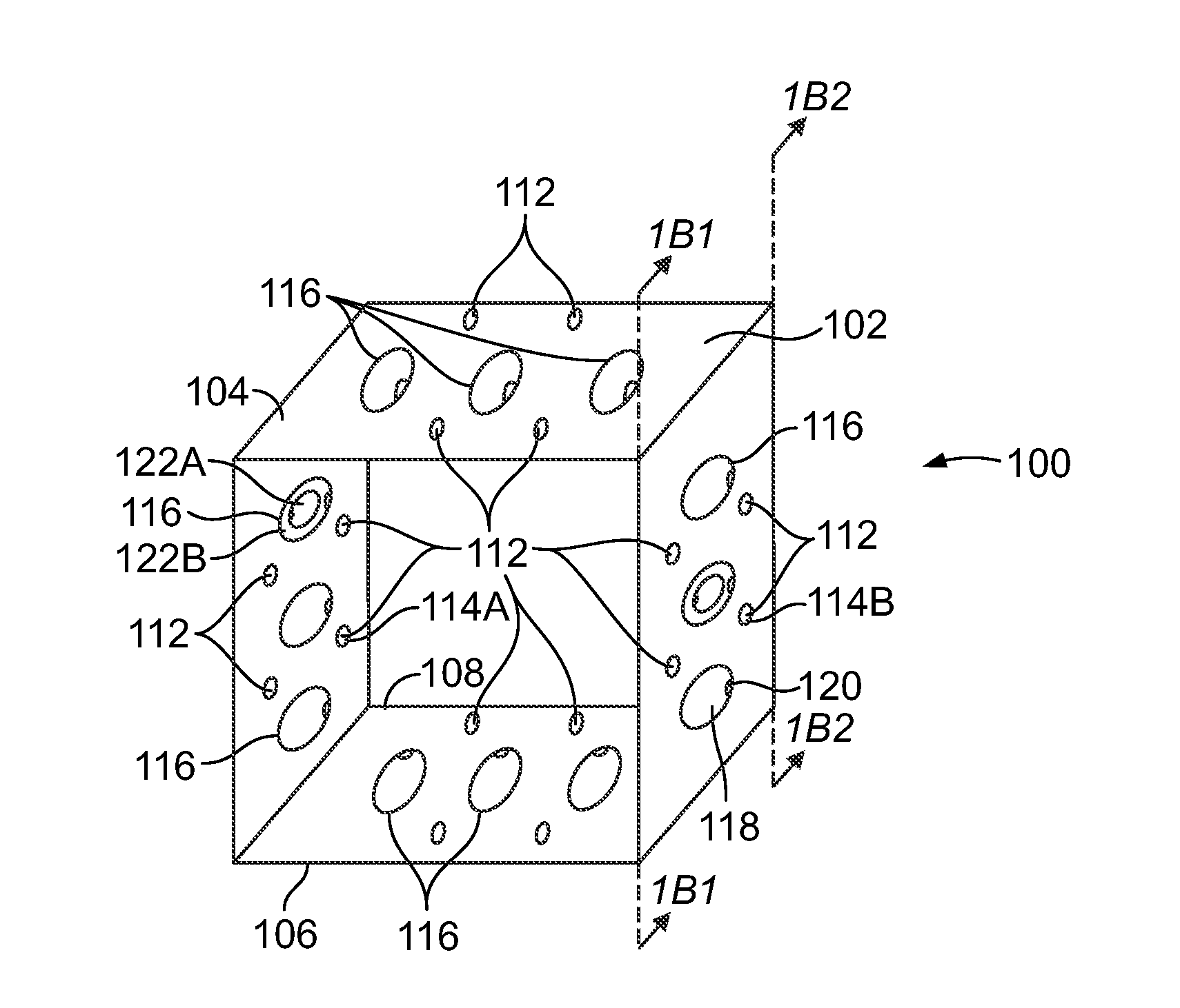
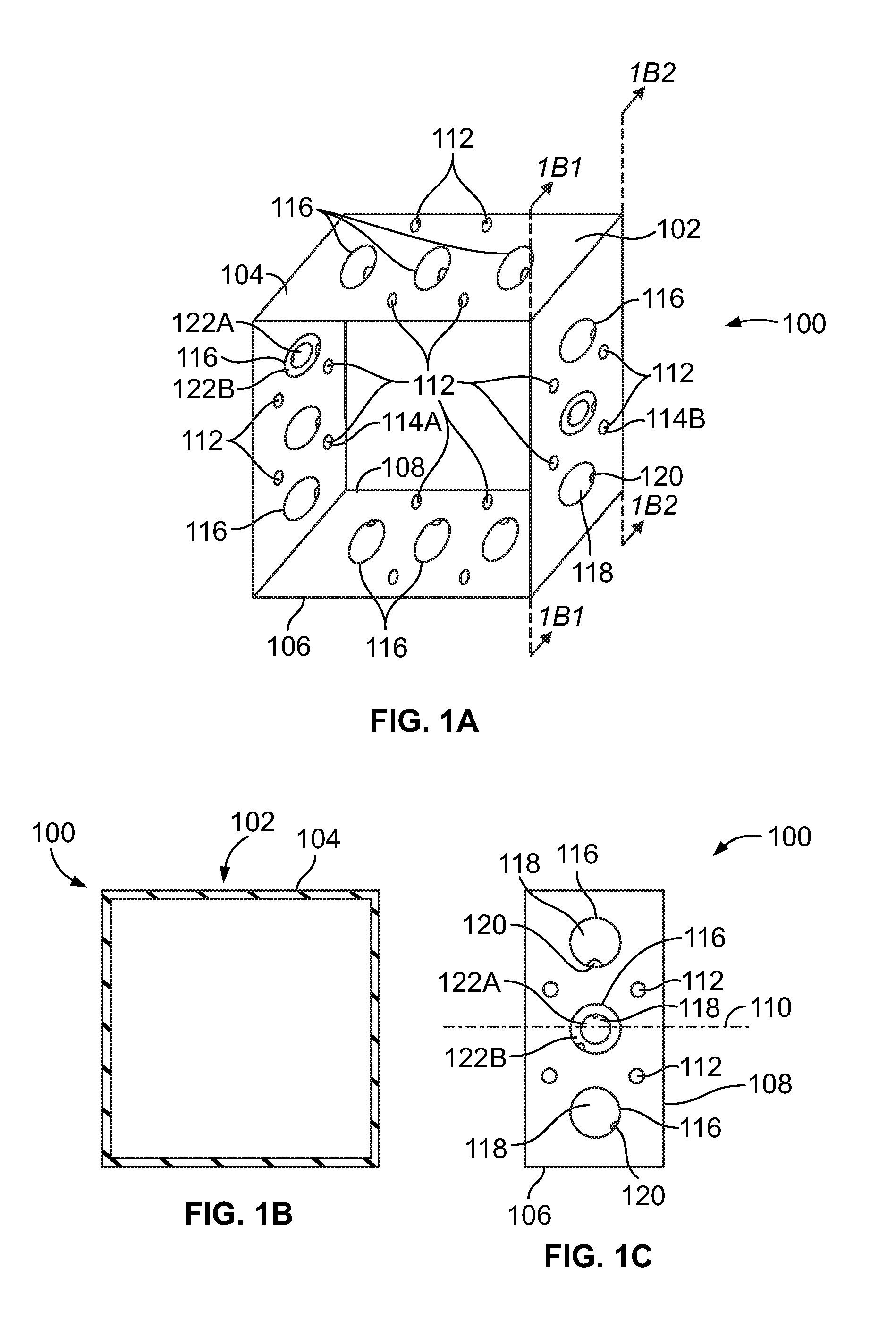
[0049]Referring now to the drawings wherein like numerals refer to like parts, FIGS. 1A-1C illustrate an embodiment of a dual-access electrical box 100 formed of a duct 102 having a sidewall 104, a first end 106, and a second end 108. The sidewall 104 defines a passageway having a generally uniform cross-sectional shape along a longitudinal axis 110 of the duct 102 between and including the first and second ends 106, 108. It is contemplated that the duct may have a cross-sectional area that is generally uniform along the longitudinal axis 110 between and including the first and second ends 106, 108. The duct 102 may also have a cross-sectional area that varies along the longitudinal axis 110 between and including the first and second ends 106, 108.

[0050]The first and second ends 106, 108 of the duct 102 have identical cross-sectional features when viewed along the longitudinal axis 110. FIG. 1B illustrates the cross-section of the duct 102 at both the first and second ends 106, 108....


PUM


Abstract

A dual-access electrical box includes a duct having a longitudinal axis, a sidewall, a first end, and a second end. At least one first aperture is disposed through the sidewall and a plurality of second apertures is disposed through the sidewall. Each of the first apertures is generally smaller than each of the second apertures and a removable plug is disposed in at least one of the second apertures. The dual-access electrical box can be attached to a cover plate or an electrical device thereby enclosing the electric cables that course through or are attached therein.

Description

CROSS-REFERENCE TO RELATED APPLICATIONS[0001]The present application claims priority from U.S. Provisional Patent Application Ser. No. 61 / 329,524, filed Apr. 29, 2010, which is hereby incorporated in its entirety.FIELD OF THE INVENTION[0002]The present invention relates to the field of construction materials, and in particular to an electrical box. More specifically, the present invention relates to a dual-access electrical box having an interior that is accessible from more than one side of the electrical box.BACKGROUND OF THE INVENTION[0003]An electrical box or junction box is a container used to conceal and isolate electrical cables and connections from their surrounding environment. Generally, electrical boxes have apertures disposed through their walls for receiving multiple conduits that cover such electrical cables or are such electrical cables that may be interconnected within the electrical box. Such interconnection facilitates a connection to other electrical devices, such...

Claims


Application Information

Patent Timeline
IPC IPC(8): H02G3/08
CPCH02G3/086
Inventor GARVIN, BARTON L.
Owner GARVIN BARTON L
Why Eureka
Try Eureka