
Apparatus and method for snoop access in a dual access, banked and pipelined data cache memory unit

a data cache and cache memory technology, applied in the field of data processing systems, can solve the problems of insufficient number of storage cell locations in the storage cell array, limitation of the execution of instructions,

Active Publication Date: 2004-08-12
ORACLE INT CORP
View PDF10 Cites 17 Cited by
  • Summary
  • Abstract
  • Description
  • Claims
  • Application Information

AI Technical Summary

Problems solved by technology

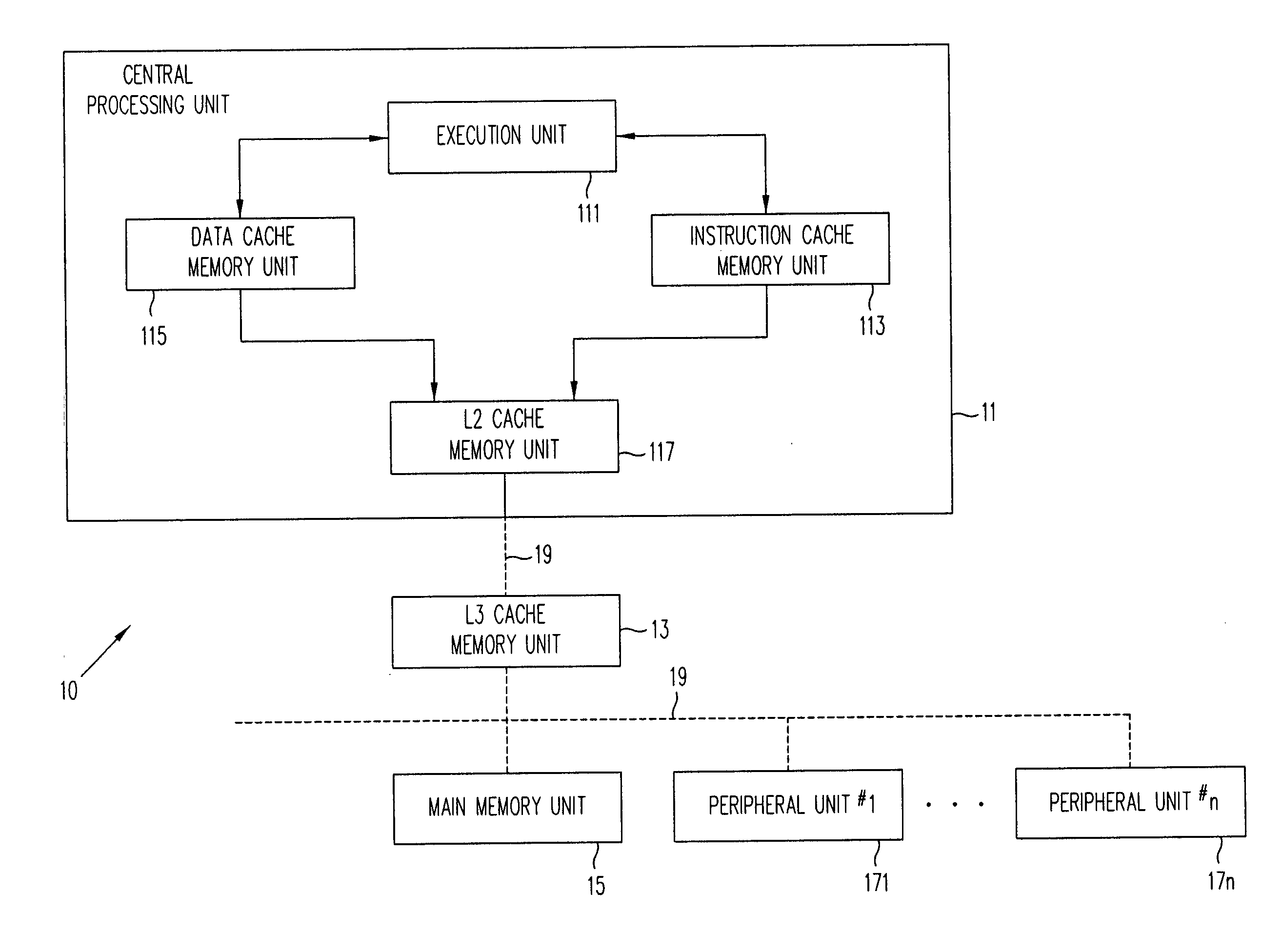
In this processing environment, the challenge has been to provide data and instruction signal groups to the execution units at a rate commensurate with the rate at which the instructions are being executed.
In addition, the modem data processing systems process data at such a rapid clock cycle that the physical dimensions over which the information must travel can provide a limitation for the execution of instructions.
However, as the speed with which instruction groups could be executed has increased, the cache unit associated with the execution unit has expanded to a size wherein the data and instruction groups could not be provided to the execution unit in a timely fashion.
The number of storage cell locations in the storage cell array is not sufficient to provide a cache memory unit location for every possible address.

Method used


Image

  • Apparatus and method for snoop access in a dual access, banked and pipelined data cache memory unit
  • Apparatus and method for snoop access in a dual access, banked and pipelined data cache memory unit
  • Apparatus and method for snoop access in a dual access, banked and pipelined data cache memory unit

Examples


Embodiment Construction

)

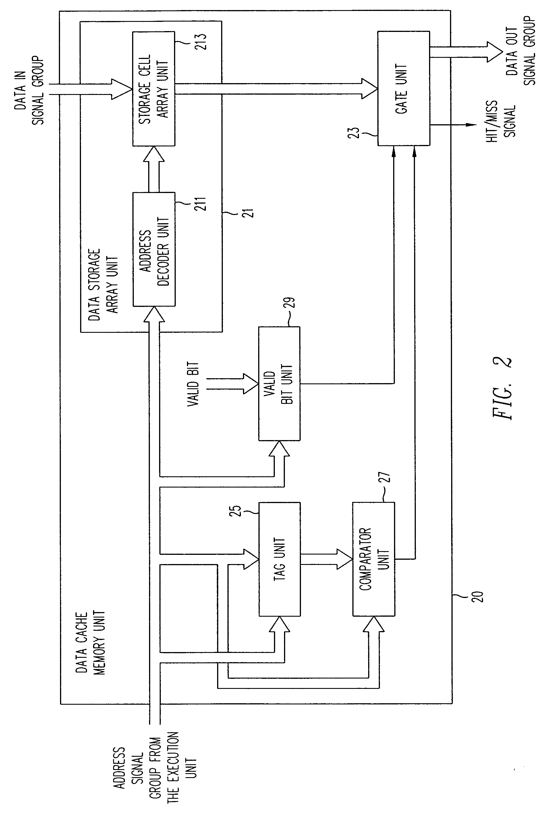
[0024] Referring to FIG. 3, the structure of the data cache memory unit 300 and associated apparatus, according to an embodiment of the present invention, is shown. The data cache memory unit 300 illustrates the implementation of a retrieval of information stored in the banked data array unit 350, i.e., the retrieval of information from a memory unit typically referred to as a READ operation. In the READ operation, the banked data array unit 350, the banked data array unit 350 including a plurality of storage cell bank units 351(0,0) through 351(M,N), can retrieve (READ) two data signal groups simultaneously (subject to the restriction that the two data signal groups are not stored in the same storage cell bank unit). The virtual address signal group VA in the execution unit 30 is described by two components RS1 and RS2. The actual virtual address signal group VA is formed by adding the components RS1 and RS2. In the execution unit 30, the components RS1 and RS2 are applied to the ...


PUM


Abstract

In a data cache unit that exchanges data signal groups with at least two execution units, the operation of the data cache unit is implemented as a three-stage pipeline in order to access data at the speed of the system clock. The data cache unit has a plurality of storage cell banks. Each storage cell bank has valid bit array unit and a tag unit for each execution unit incorporated therein. Each valid bit array unit has a valid / invalid storage cell associated with each data group stored in the storage cell bank. The valid bit array units have a read / write address port and snoop address port. During a read operation, the associated valid / invalid signal is retrieved to determine whether the data signal group should be processed by the associated execution unit. In a write operation, a valid bit is set in the valid / invalid bit location(s) associated with the storage of a data signal group (or groups) during memory access. The valid bit array unit responds to a snoop address and a control signal from the tag unit to set an invalid bit in a valid / invalid bit address location associated with the snoop address. The tag unit can be divided into a plurality of tag subunits to expedite processing.

Description

[0001] 1. Field of the Invention[0002] This invention relates generally to data processing systems and, more particularly, to a data cache memory unit forming part of a central processing unit. The data cache unit stores data groups that are required by an associated execution unit of the central processing unit. Because a data signal group stored in the data cache memory unit can be changed in some other part of the data processing system, apparatus must be provided to insure that the execution unit does not process an invalid data signal group.[0003] 2. Description of the Related Art[0004] The ability of data processing systems to execute instructions has increased to such an extent that one figure of merit of a data processing unit is the number of instructions executed per second. In this processing environment, the challenge has been to provide data and instruction signal groups to the execution units at a rate commensurate with the rate at which the instructions are being exec...

Claims


Application Information

Patent Timeline
IPC IPC(8): G06F12/08
CPCG06F12/0831G06F12/0855G06F12/0846
Inventor THATIPELLI, KRISHNA M.TZENG, ALLAN
Owner ORACLE INT CORP
Learn More