Warning device for monitoring a health status of a bearing having a close range wireless interface

a technology of a warning device and a close range wireless interface, which is applied in the direction of instruments, mechanical equipment, rotary machine parts, etc., can solve the problems of installation cos

Inactive Publication Date: 2014-06-05
AB SKF
View PDF15 Cites 16 Cited by
  • Summary
  • Abstract
  • Description
  • Claims
  • Application Information

AI Technical Summary

Problems solved by technology

Also, a major consideration is the installation cost, especially for cabling.

Method used


Image

  • Warning device for monitoring a health status of a bearing having a close range wireless interface
  • Warning device for monitoring a health status of a bearing having a close range wireless interface
  • Warning device for monitoring a health status of a bearing having a close range wireless interface

Examples


embodiment 10

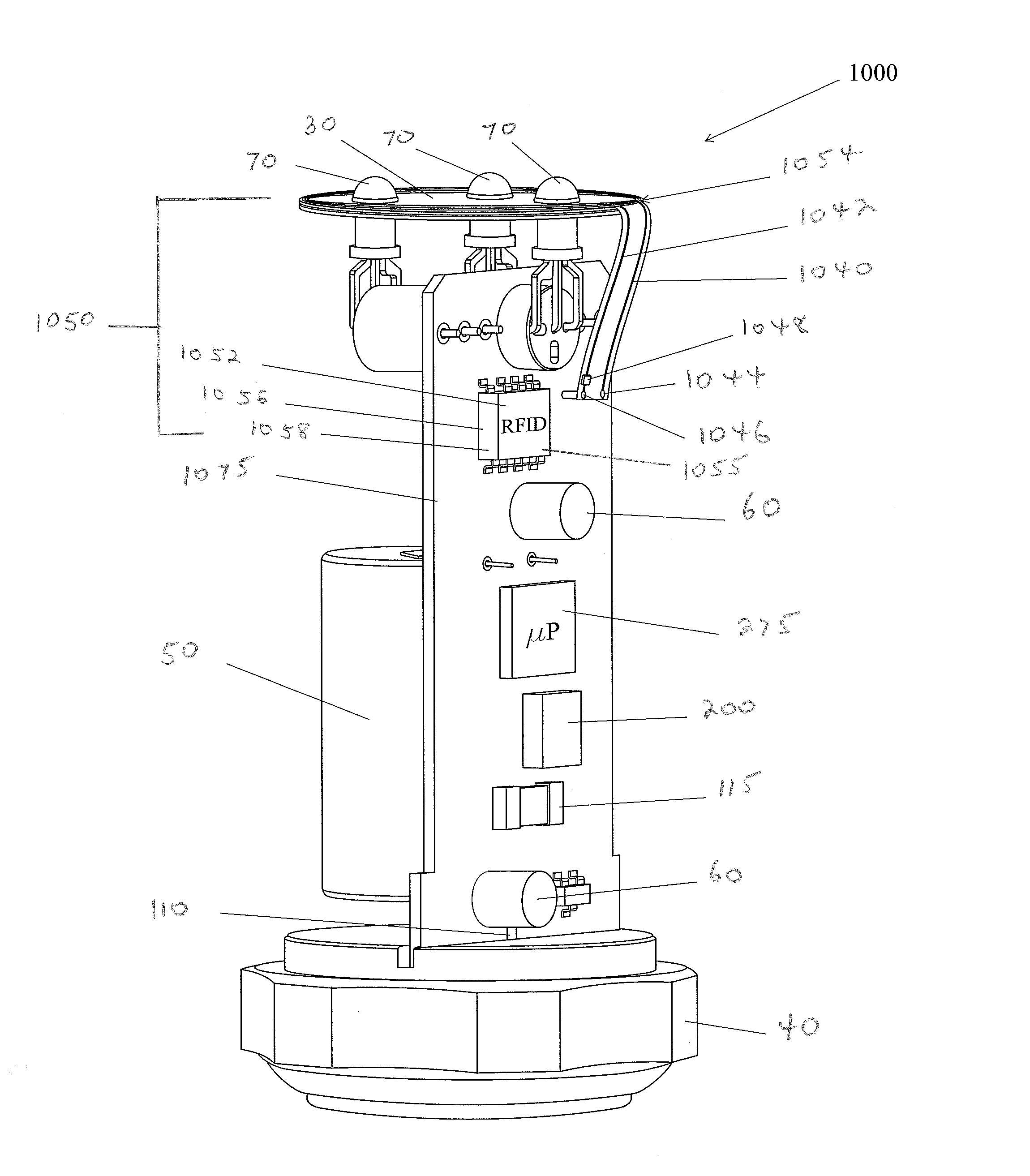
[0058]A warning device 1000 for monitoring a health status of a bearing mounted to a piece of rotating machinery 400 in an industrial environment 500 having a close range wireless interface 1050 is illustrated in FIG. 7. The warning device 1000 of this embodiment is the same as that of the prior embodiment 10 except for the introduction of the close range wireless interface 1050.

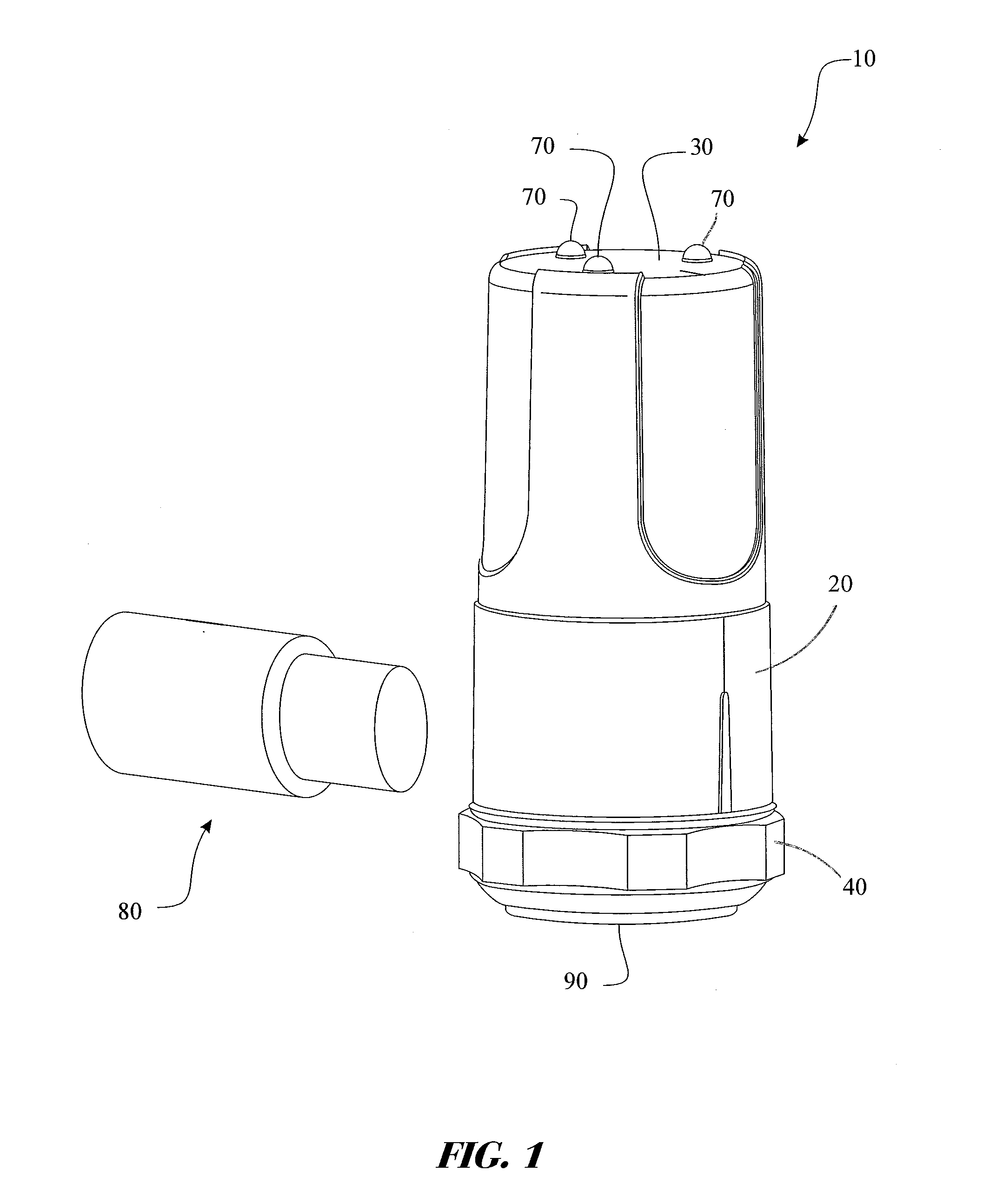
[0059]As previously disclosed, the warning device 10 includes a body portion 20 that is connected to a top portion 30 and a base portion 40. A battery 50 for powering the device is also included. Here, the battery 50 provides power to the RFID device 1000 for at least 3 years of normal operation with a single alarm detection. In addition, at least one sensor 60 and / or accelerometer 115 for sensing at least one of a velocity, an enveloped acceleration and a temperature reading of the bearing is provided. At least one illuminating device 70 for displaying the health status of the bearing according to input fro...

embodiment 1000

[0073]Now referring to the embodiment of warning device 1200 that is illustrated in FIG. 9, everything is the same with respect to the previous embodiment 1000 except antenna 1254 includes at least two tuned coiled loops of copper wire 1234 that lay on top of the top portion 30. Here, the ends of the copper wire are terminated to solid leads 1240, 1242, which in turn get staked into PBC 1275. Here again, the antenna is configured for receiving and transmitting the modulated and demodulated signals. A bus connects the antenna to the RFID tag 1052 and on to the microprocessor 275. A digital bus is employed in the current embodiment, but there are other types of buses that could be utilized to accomplish this function. For example, a high speed serial bus could be provided.

[0074]Now referring to the embodiment of warning device 1300 that is illustrated in FIG. 10, everything is the same with respect to the previous embodiment 1000 except antenna 1354 includes a coiled inductor directly...


PUM


Abstract

A warning device having a close range wireless interface is provided. The warning device includes a body portion, top portion, a base portion, a microcontroller for controlling the device, a battery, at least one sensor for sensing at least one of a velocity, an enveloped acceleration and a temperature reading of the bearing, and at least one LED for displaying the health status of the bearing.
The close range wireless interface includes an RFID tag having an integrated circuit, and a radio, an antenna for receiving and transmitting modulated and demodulated signals, and a digital bus connecting the microcontroller to the RFID tag. The microcontroller stores at least one of the sensed velocity, enveloped acceleration and the temperature values into a memory disposed within the RFID tag. The memory is a dual access memory that enables data transfer via the RFID radio or via the digital bus.

Description

CROSS-REFERENCE TO RELATED APPLICATIONS[0001]This application is a Continuation in Part Application claiming the benefit of priority to International Patent Application No. PCT / US2012 / 67293 filed on Nov. 30, 2012, which claims the benefit of priority to U.S. Provisional Patent Application no. 61 / 577,884, filed on Nov. 20, 2011.FIELD OF THE INVENTION[0002]The present disclosure generally relates to a device for monitoring a health status of a bearing mounted to a piece of rotating industrial machinery. More particularly, the present disclosure relates to a warning device permanently mounted to a piece of rotating industrial machinery having a close range wireless interface.BACKGROUND OF THE INVENTION[0003]The present invention provides a simple, low cost way to monitor the status of a bearings health in a piece of rotating industrial equipment. Historically simple transmitter based systems have been employed on industrial machinery for overall machine health and detection of bearing ...

Claims


Application Information

Patent Timeline
Patent Type & Authority Applications(United States)
IPC IPC(8): F16C41/00G08B21/18
CPCG08B21/187F16C41/008F16C19/525F16C19/527F16C2300/02F16C2233/00
Inventor MURPHY, JON D.
Owner AB SKF
Why Eureka
Try Eureka