Trigger valve controlling device for pneumatic nail gun

a controlling device and nail gun technology, applied in the direction of nailing tools, manufacturing tools, stapling tools, etc., can solve the problems of large receiving space in the gun body, high manufacturing cost, and difficult manufacture of the gun body

Inactive Publication Date: 2011-11-03
DE POAN PNEUMATIC
View PDF8 Cites 14 Cited by
  • Summary
  • Abstract
  • Description
  • Claims
  • Application Information

AI Technical Summary

Benefits of technology

[0011]An upper ring surface is formed on the top of the valve sleeve and is exposed in the middle chamber, the valve sleeve, together with the upper ring surface, is capable of being pushed by the high pressure air in the middle chamber to move linearly downward, the lower ring surface is formed on the outer wall of the valve sleeve and is exposed in the front passageway, the valve sleeve, together with the lower ring surface, is capable of being pushed by the high pressure air in the front passageway to move linearly upward.

Problems solved by technology

2. A valve controlling device is extra disposed in the gun body and has a complicated structure with too many components, so that a larger receiving space in the gun body is required.
Thus, it is difficult to manufacture the gun body and a manufacturing cost is high.

Method used


Image

  • Trigger valve controlling device for pneumatic nail gun
  • Trigger valve controlling device for pneumatic nail gun
  • Trigger valve controlling device for pneumatic nail gun

Examples


Embodiment Construction

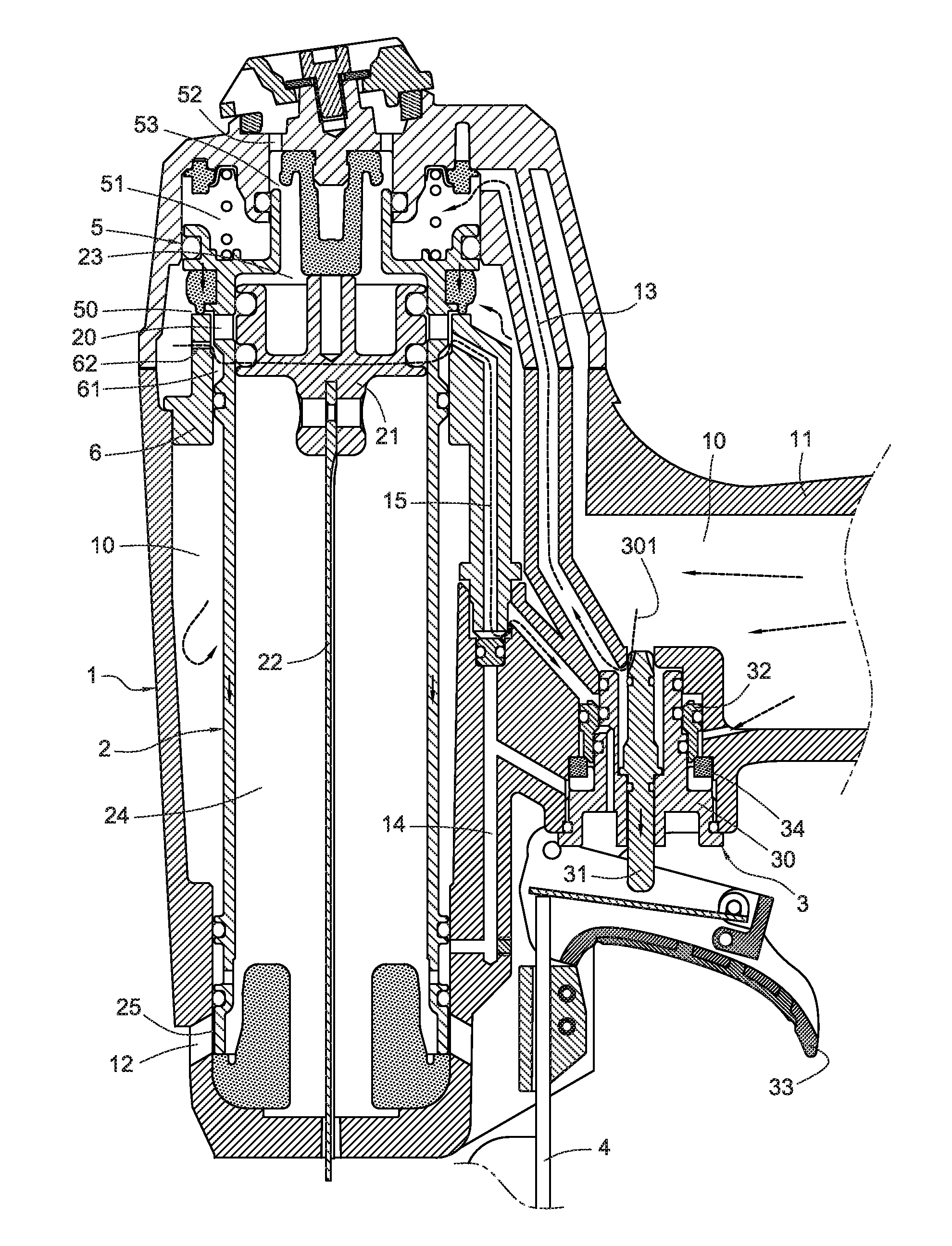
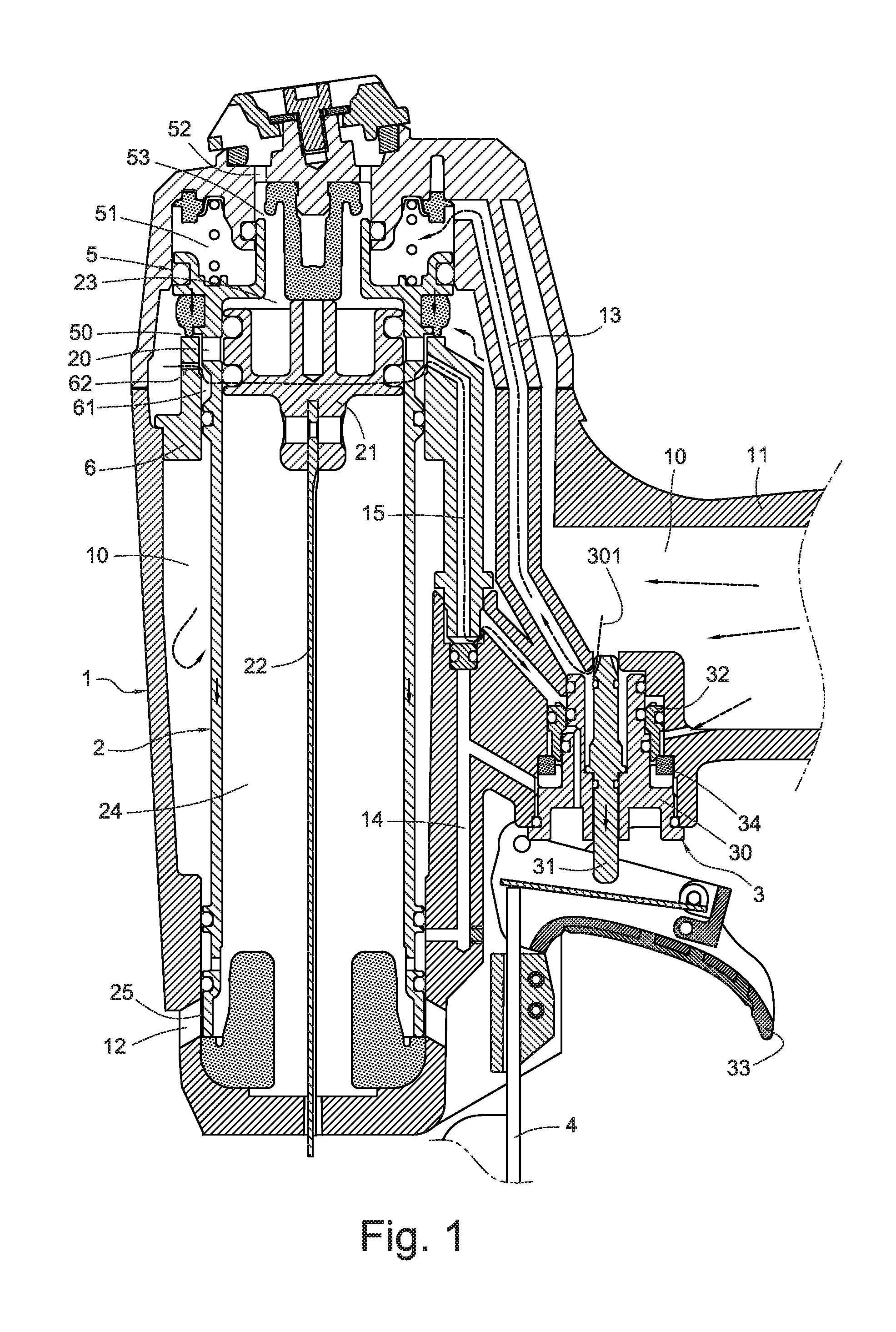
[0020]FIG. 1 shows a cutaway view of a trigger valve controlling device for a pneumatic nail gun in accordance with the present invention. The trigger valve controlling device for a pneumatic nail gun is disposed in a gun body 1 of the pneumatic nail gun. A cylinder 2 is disposed in the gun body 1, and a piston 21 is slidably connected to the cylinder 2. A bottom of the piston 21 is connected to a hitting bar 22. The piston 21 separates the cylinder 2 into a top cylinder chamber 23 and a bottom cylinder chamber 24. A plurality of main air chambers 10 are formed in the gun body 1. The main air chambers 10 are filled with a high pressure air and are intercommunicated with each other. The main air chambers 10 are disposed between a periphery of the cylinder 2 and a handle 11, and are configured to receive the high pressure air continuously flowing from a rear of the handle 11.

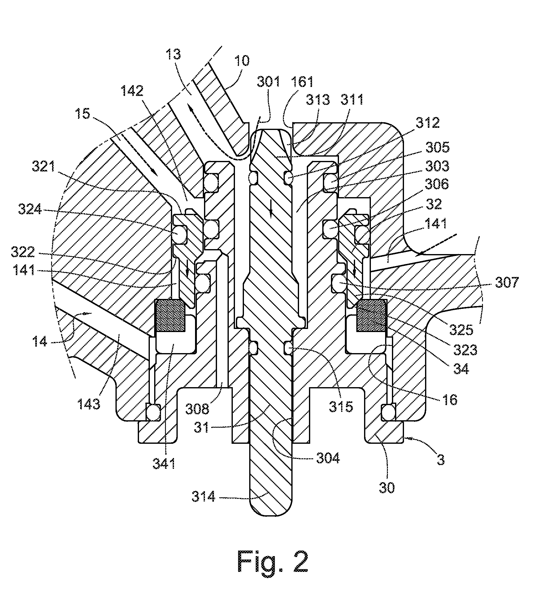
[0021]The gun body 1 has a trigger valve 3 adjacent to the handle 11. The trigger valve 3 is intercommunicated ...


PUM

PropertyMeasurementUnit
pressureaaaaaaaaaa
areaaaaaaaaaaa
pneumatic poweraaaaaaaaaa

Abstract

A trigger valve controlling device for a pneumatic nail gun includes a main air passageway, a valve sleeve and a main air valve opening. The valve sleeve separates the main air passageway into a front passageway, a middle chamber and a rear passageway. After hitting nails, a high pressure air in the trigger valve controlling device is capable of driving a hitting bar of the pneumatic nail gun to move upward to reset.

Description

BACKGROUND[0001]The present invention relates to a trigger valve controlling device and, more particularly, to a trigger valve controlling device for a pneumatic nail gun, a valve sleeve of the trigger valve which can detect an opening or closing status of a top air outlet of a cylinder, and an air driving passageway for controlling high pressure air to drive a hitting bar to reset.[0002]A pneumatic nail gun having a pneumatic power source is a type tool used to drive nails into wood or some other kind of material. Usually, a safe sliding rod is arranged on a periphery of a gun body. The safe sliding rod is used to control operation sequence of hitting nails. The gun body has a plurality of main air chambers, a cylinder, a piston slidably connected in the cylinder, a hitting bar mounted to a bottom of the piston and a trigger valve for driving the hitting bar to hit nails therein. The main air chambers are configured to receive a high pressure air and keep a pressure of the high pre...

Claims


Application Information

Patent Timeline
Patent Type & Authority Applications(United States)
IPC IPC(8): B25C1/04
CPCB25C1/047
Inventor WU, I-TSUNG
Owner DE POAN PNEUMATIC
Why Eureka
Try Eureka