Functional switching set of servo actuator

Inactive Publication Date: 2006-11-01
CHINA COAL TECH & ENG GRP SHANGHAI RES INST
View PDF0 Cites 7 Cited by
  • Summary
  • Abstract
  • Description
  • Claims
  • Application Information

AI Technical Summary

Problems solved by technology

[0003] 1. The energy loss is large and the temperature rise of the system is high. The former involves a decline in operating economic benefits, and the latter will significantly increase the failure rate of various components of the system. These defects are formed because the system requires a stable constant pressure source, and the pressure output of the pump It has nothing to do with the change of load. When running at low load, there will be a large throttling and overflow loss, and the temperature rise of the system will increase accordingly; high temperature rise
[0004] 2. The speed stability of the existing hydraulic speed servo system is low, thereby reducing the output quality of the actuator

Method used


Image

  • Functional switching set of servo actuator
  • Functional switching set of servo actuator
  • Functional switching set of servo actuator

Examples


Embodiment Construction

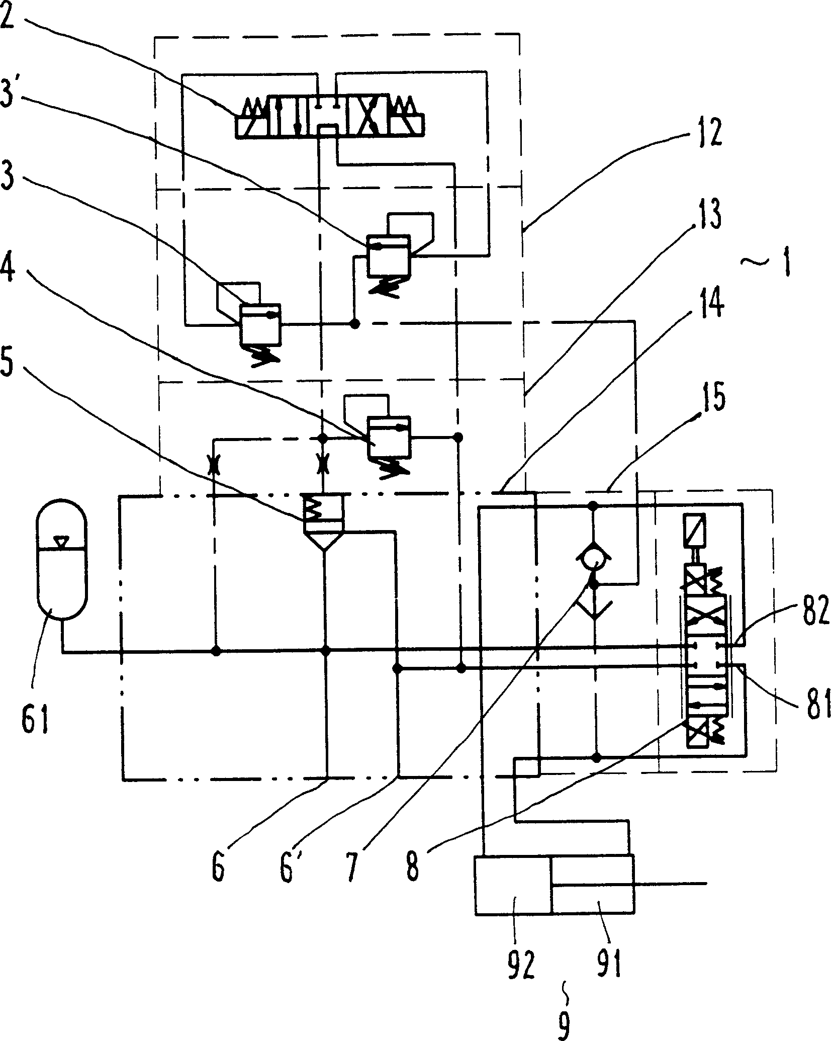
[0011] refer to figure 1 , the servo actuator function valve group is a combined valve block 1, which is composed of each valve block 12, 13, 14, 15, and each valve block 12, 13, 14, 15 is fixed as a whole with bolts, and its interior is provided with The flow passages of various valve parts can be connected, which can reduce the adverse influence of pipeline effects on the frequency response of the system.

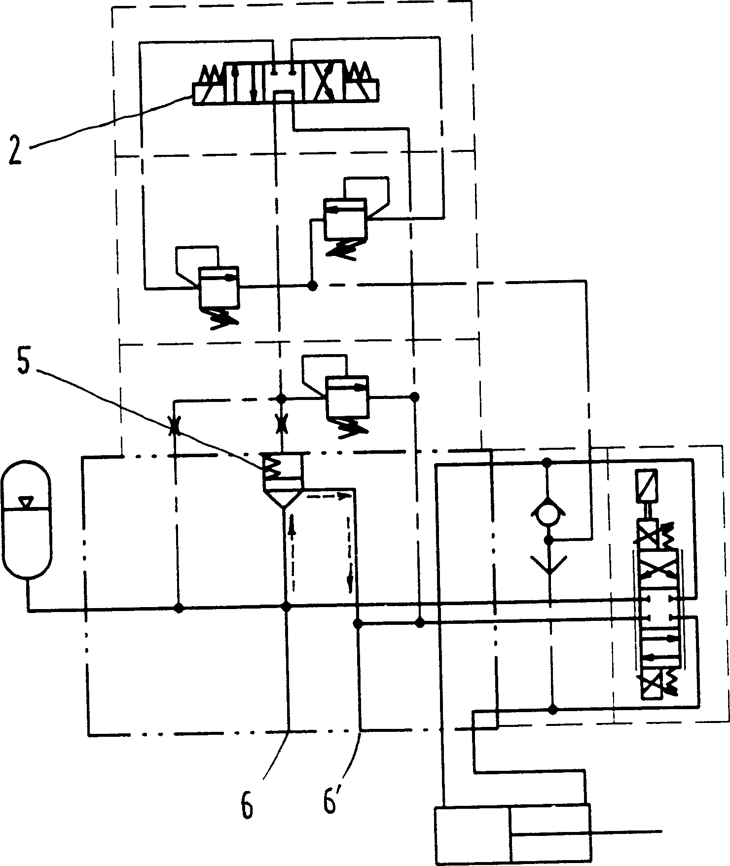
[0012] An electromagnetic reversing valve 2 is arranged on the valve block 12, and the electromagnetic reversing valve 2 is respectively connected with three overflow valves 3, 3', 4, pressure compensator 5 and oil return port 6', and the electromagnetic reversing valve 2 is a system Unloading valve and compensating pressure selection valve, when the valve is de-energized and in the neutral position, the entire flow of the system returns to the oil tank through the pressure compensator, such as figure 2 As shown by the dotted arrow, the unloading of low pressure and ful...


PUM


Abstract

In the invention, a relief valve is connected with a magnetic reserving valve, a shuttle valve, a proportional direction valve and an actuator. Another relief valve is in parallel on one side of the said relief valve. A pressure compensator is connected with a magnetic reserving valve, an oil inlet, and an oil return port. One end of the shuttle valve is connected with an oil outlet of the proportional directional valve and a working cavity of the actuator. The other end of the shuttle valve is connected with another oil outlet of the proportional directional valve and another working cavity of the actuator.

Description

Technical field: [0001] The present invention relates to a fluid distribution or supply device characterized by the control of a suitable servo motor, in particular a valve group operated by an electronic control device. Background technique: [0002] In many industries such as machinery, chemical industry, mining, etc., many automatic equipment that require high power and high force / torque output widely use hydraulic speed servo systems. The common speed control loop is a loop that uses proportional flow valve speed regulation, including: Oil inlet throttle speed regulation, oil return throttle speed regulation and bypass throttle speed regulation, etc., that is, the basic working principle of the system is to achieve speed regulation by throttling, and the circuit includes actuators, proportional flow valves and other corresponding accessories. Its structure is relatively simple, and it can also realize automatic control of speed and remote control of speed, etc.; but the ...

Claims


Application Information

Patent Timeline
Patent Type & Authority Applications(China)
IPC IPC(8): F15B13/02F15B11/04F15B13/044
Inventor 陈忠强芮丰冯晓迪邱士浩
Owner CHINA COAL TECH & ENG GRP SHANGHAI RES INST
Why Eureka
Try Eureka