Non-contact valve plate flatness detection device and method

A flatness detection, non-contact technology, applied in measurement devices, mechanical measurement devices, optical devices, etc., can solve the problems of inability to meet the buyer's product quality inspection, inefficient detection methods, and poor reliability of detection results. Compact structure, high speed stability and small motion error

Pending Publication Date: 2019-12-03
CHINA JILIANG UNIV
View PDF0 Cites 7 Cited by
  • Summary
  • Abstract
  • Description
  • Claims
  • Application Information

AI Technical Summary

Problems solved by technology

With the increasing complexity of the shape of the distribution plate and the rapid development of science and technology, higher and newer requirements have been put forward for the flatness detection of the distribution plate in practical applications, and even the flatness error is required to reach 5μm, which requires the manufacturer to check each distribution plate. However, the traditional detection method is inefficient, labor-intensive, prone to errors due to visual fatigue after long-term work, and the probe will wear out after long-term use, requiring regular corrections, and the reliability of the detection results is poor, which is no longer satisfactory Buyers' requirements for product quality inspection and the needs of enterprises for their own transformation and development

Method used


Image

  • Non-contact valve plate flatness detection device and method
  • Non-contact valve plate flatness detection device and method
  • Non-contact valve plate flatness detection device and method

Examples


Embodiment Construction

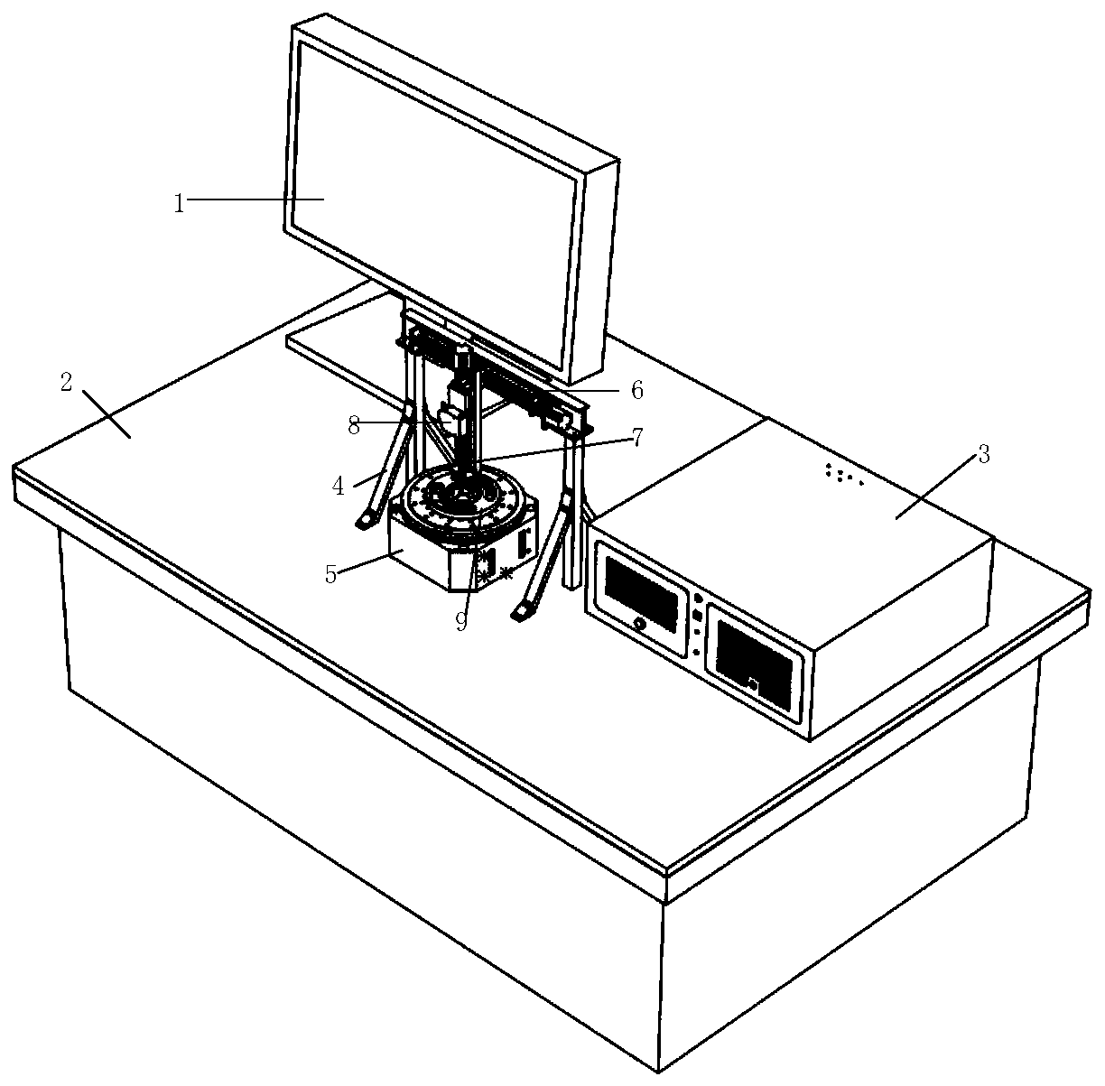
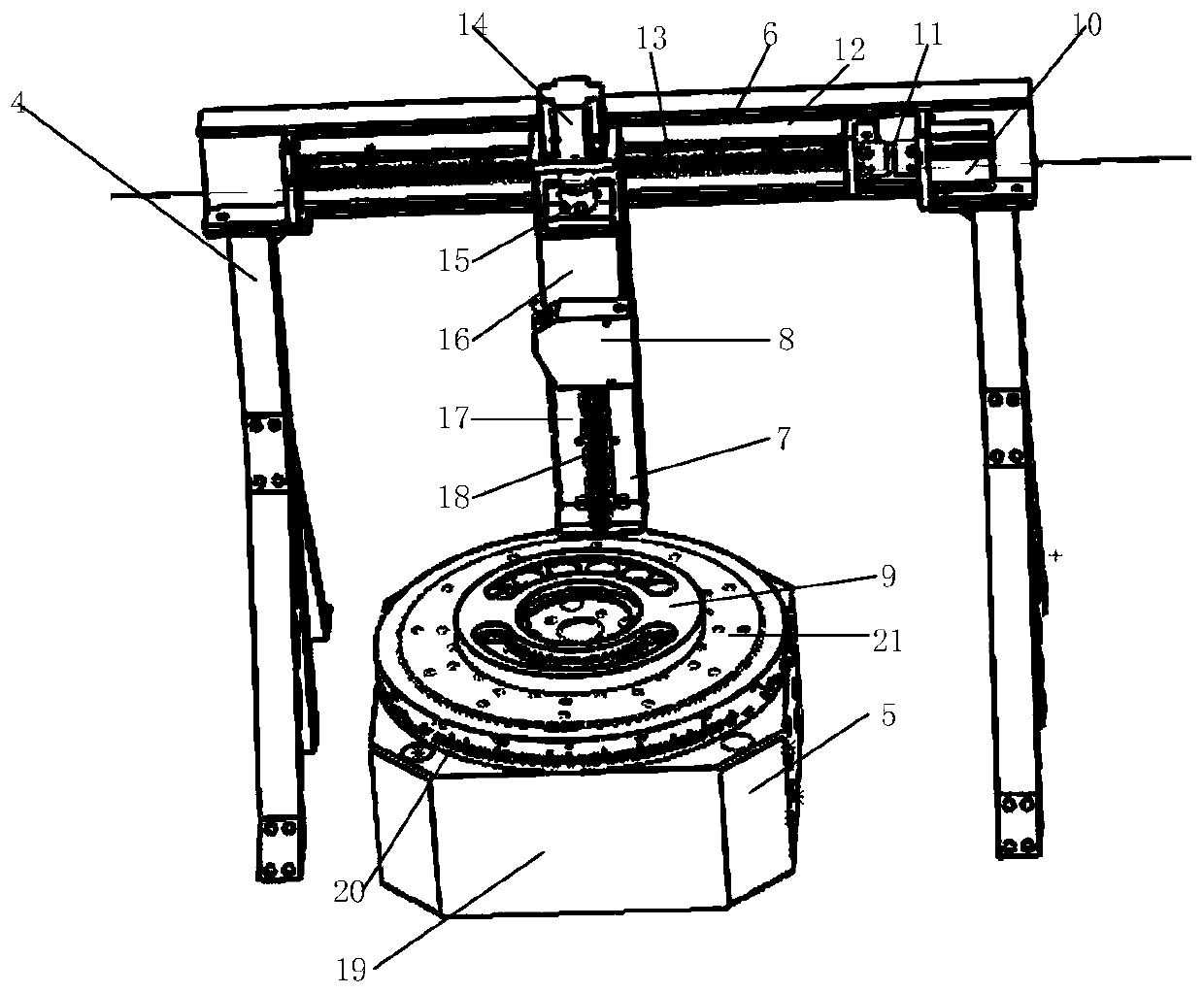
[0035] like figure 1 , 2As shown, the distribution plate 9 is placed on the air-floating turntable 5, the gantry 4 and the air-floating turntable 5 are placed on the marble table 2, the X-guiding rail is fixed on the gantry frame, and the Z-guiding rail is fixed on the X-guiding rail slider 13, the Z guide rail 7 slides with the X guide rail slider 13, and the laser displacement sensor 8 is installed on the Z guide rail connecting plate 16, through the Z direction motor 14 and the Z direction coupling 15, along with the Z guide rail slider 16 Swipe up and down. The industrial computer 3 controls the corresponding motors 10 and 14 by controlling the motion control card, and then controls the movement of the X guide rail, the Z guide rail and the air bearing turntable.

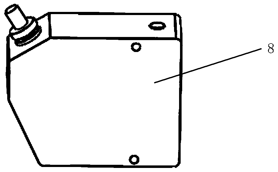
[0036] like image 3 As shown, the general structure of the laser displacement sensor is shown in the figure, and the measurement accuracy is 0.2 μm.

[0037] like Figure 4 As shown, the test bench and the...


PUM


Abstract

The invention discloses a non-contact valve plate flatness detection device and method. An X-direction guide rail is fixed on a cross beam of a portal frame; a Z-direction guide rail is fixed on an X-direction guide rail sliding block; and a laser displacement sensor is fixed on a Z-direction guide rail sliding block. The laser displacement sensor can be adjusted to an optimal measurement distanceand workpieces with different heights can be measured. A valve plate is arranged on an air floatation turntable; and the X-direction guide rail sliding block is moved to change the distance from thelaser displacement sensor to the center. The air floatation turntable rotates to carry out measurement for one circle with 12 points; after measurement of two circles, measured data are uploaded to acomputer; error compensation and cross criterion plane fitting of a minimum containment area method are performed by using an application program; and calculation is performed to obtain a final planeness error value displayed on a display screen. Therefore, flatness detection can be automatically completed; more data can be obtained; the actual surface of a measured workpiece can be accurately reflected; and no measuring head wear error exists.

Description

technical field [0001] The invention relates to a detection device suitable for flatness measurement, in particular to a detection device suitable for non-contact flow distribution plate flatness measurement. Background technique [0002] The distribution plate is an important component in the hydraulic system of the excavator. Its flatness will affect the power consumption and service life of the hydraulic system, and then affect the normal operation of the excavator. In order to prevent the distribution plate with poor flatness from flowing into the subsequent assembly and production of the excavator and causing the excavator to fail to work normally, the distribution plate must undergo strict flatness testing before leaving the factory. [0003] At present, relevant companies mainly use the manual operation of the dial indicator to complete the detection of the flatness of the distribution plate. Position, then read the indicated value of the pointer of the dial gauge, m...

Claims


Application Information

Patent Timeline
Patent Type & Authority Applications(China)
IPC IPC(8): G01B11/30G01B5/00
CPCG01B5/0004G01B11/30
Inventor 郑莹洁李东升蔡晋辉胡佳成
Owner CHINA JILIANG UNIV
Why Eureka
Try Eureka