Antenna radar system and method for its operation

a radar system and antenna aperture technology, applied in the field of antenna radar system, can solve the problem of not being able to provide the same antenna aperture for lrr and srr functions

Inactive Publication Date: 2011-11-03
ROBERT BOSCH GMBH
View PDF0 Cites 17 Cited by
  • Summary
  • Abstract
  • Description
  • Claims
  • Application Information

AI Technical Summary

Problems solved by technology

For these reasons, it is not possible to provide the same antenna aperture for the LRR and SRR functions.

Method used


Image

  • Antenna radar system and method for its operation
  • Antenna radar system and method for its operation
  • Antenna radar system and method for its operation

Examples


Embodiment Construction

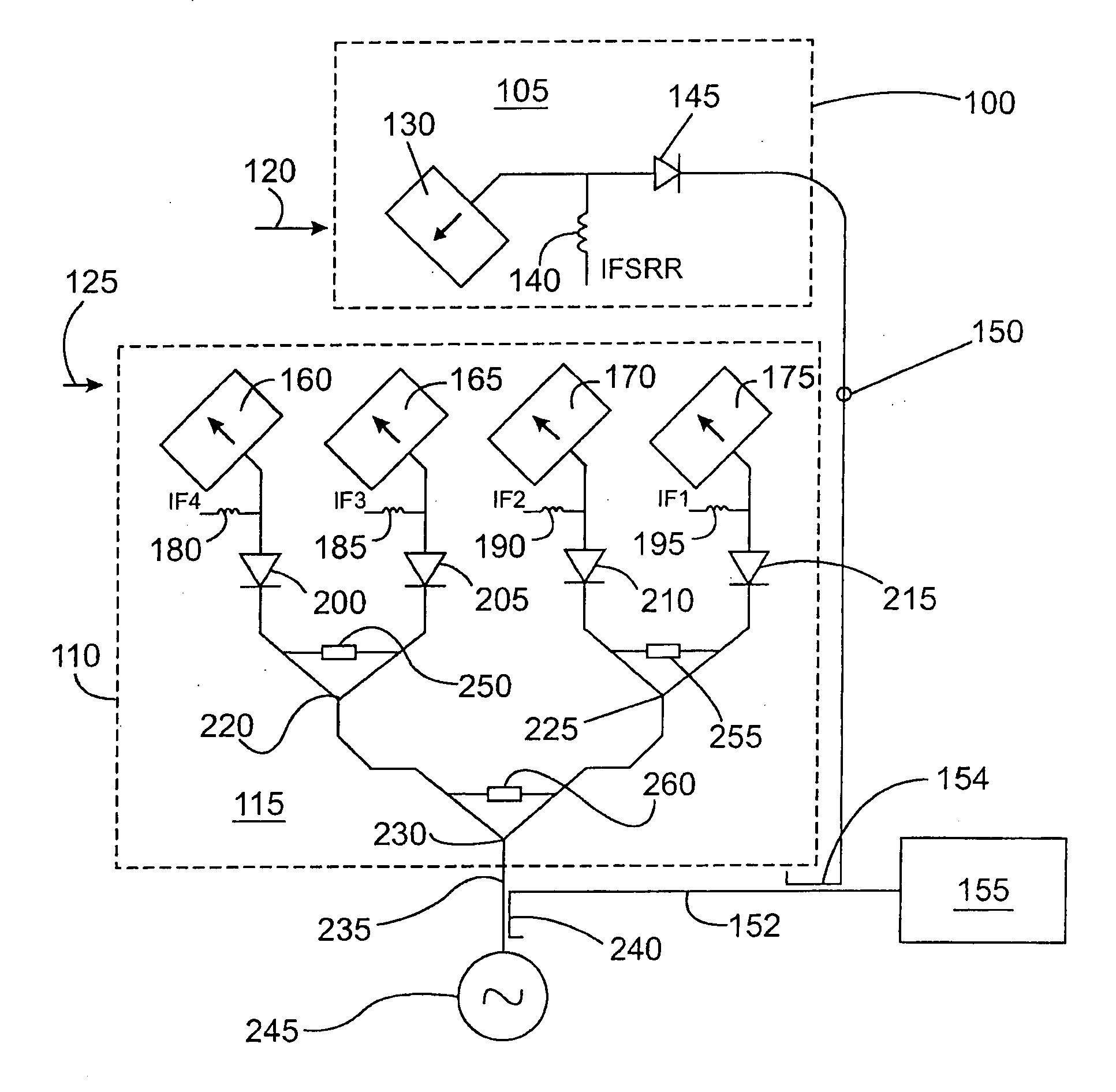
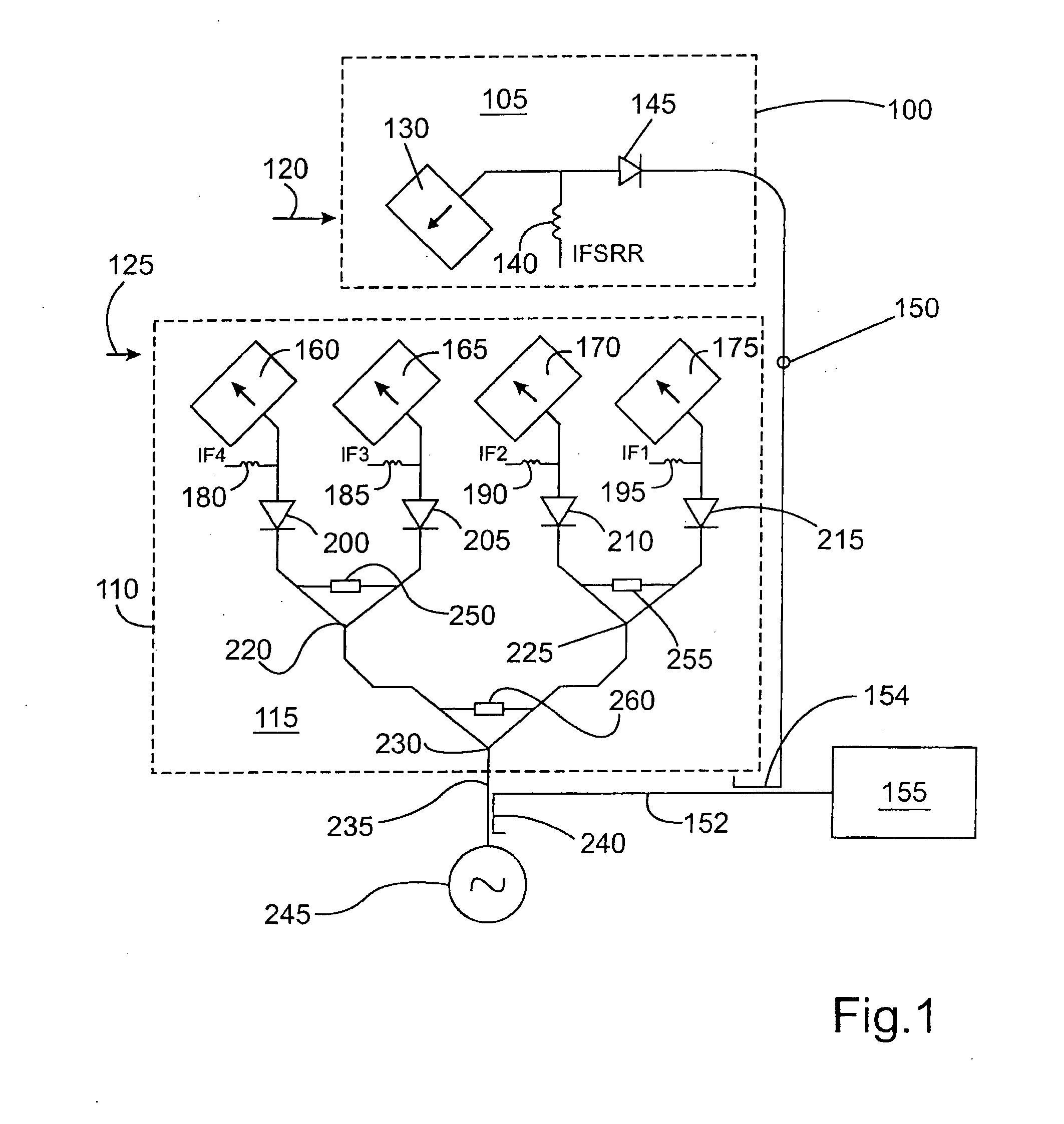
The antenna radar system schematically shown in FIG. 1 includes a short-range function 105, delimited by a first dashed line 100, and a long-range function 115 (“LRR feed”), delimited by a second dashed line 110. Feed 130 (“SRR feed”) for SRR function 105 and feeds 160, 165, 170, 175 for LRR function 115 are situated separately in the present exemplary embodiment. SRR function 105 and LRR function 115 are operated synchronously in the exemplary embodiment, i.e., not using an above-mentioned changeover switch (such as a multiplexer) in time-division multiplex operation.

SRR function 105 includes a monostatic antenna formed by a “patch array”130, the technical details of this patch array 130 not being discussed in the present context. Such a patch array for a high-frequency antenna is described in detail, for example, in the patent application having the applicant file number R. 307998, filed at the same time by the applicant. Monostatic means that antenna 130 is not implemented as non...


PUM


Abstract

In an antenna radar system including a short-range function and a long-range function which is situated separately from the short-range function, the short-range function and the long-range function having different antenna apertures, means are provided for mutual cross-polarization of the signals emitted and received using the short-range function and the long-range function, through which the most efficient possible signal-technology decoupling between the short-range function and the long-range function is achieved.

Description

FIELD OF THE INVENTIONThe present invention relates to an antenna radar system, which is preferably usable in automobile technology, as well as a method for operating such an antenna radar system according to the definitions of the species in the independent claims.BACKGROUND INFORMATIONMonostatic antennas are typically used in radar systems relevant here in the field of automobile technology, in which a shared antenna lens is used for emitted and received signals (TX / RX feeds). The polarization axes, i.e., the axes of the associated electrical field vectors of these two signals, usually have an angle of 45° in the cited radar systems, in order to ensure that the signals originating from an oncoming vehicle equipped with an identical radar are received cross-polarized in relation to the received signal of the host vehicle. Because of this measure, disturbing interference between the signals of the two vehicles is effectively suppressed.Until now, usually only long-range radar (LRR) ...

Claims


Application Information

Patent Timeline
Patent Type & Authority Applications(United States)
IPC IPC(8): G01S13/00G01S13/08G01S13/931
CPCG01S7/032G01S7/036H01Q21/24G01S13/87G01S13/931G01S13/003
Inventor HILDEBRANDT, JUERGENHAUK, JOACHIMREICHE, MARTIN
Owner ROBERT BOSCH GMBH
Why Eureka
Try Eureka