In-vehicle device

Active Publication Date: 2011-11-03
CLARION CO LTD
View PDF3 Cites 13 Cited by
  • Summary
  • Abstract
  • Description
  • Claims
  • Application Information

AI Technical Summary

Benefits of technology

[0017]According to the present invention, it is possible to display an image in which a semi-transparent graph, decorations and the like are depicted agai

Problems solved by technology

However, generation of a complex image for each change of a measured value entails a higher proces

Method used


Image

  • In-vehicle device
  • In-vehicle device
  • In-vehicle device

Examples


Example

[0025]Now, an embodiment of the present invention will be described referring to the drawings.

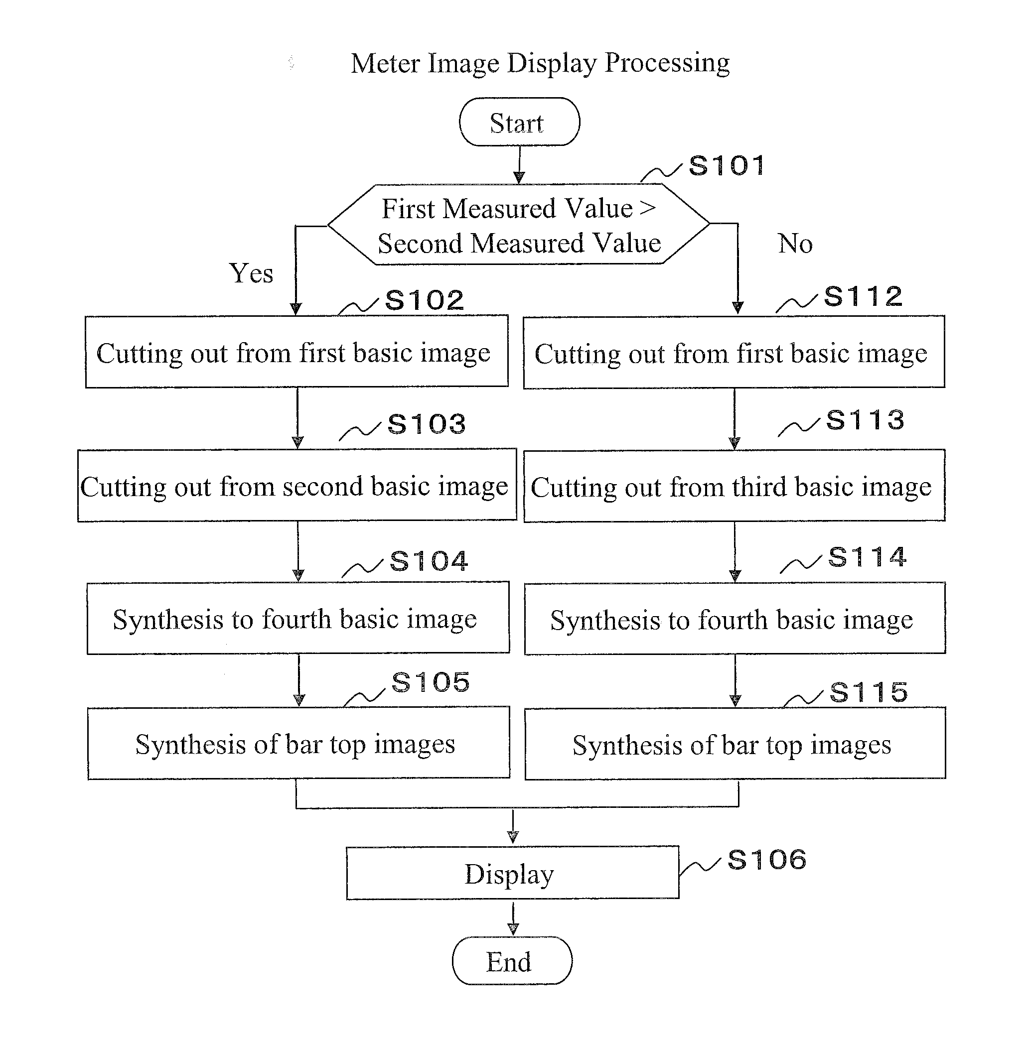
[0026]First, an outline of a meter image displayed on an in-vehicle device of the present embodiment will be described. As shown in FIG. 7, the in-vehicle device of the present embodiment displays two measured values (values to be outputted) at the same time by a meter image 300 that includes two bar graphs 302 and 304. The larger the measured value to be displayed is, the more the length of each bar graph 302, 304 grows from the lower end of a dial 301 toward the upper end.

[0027]Further, the in-vehicle device displays the bar graphs 302 and 304 such that the first bar graph 302 appears to be superimposed upon the second bar graph 304.

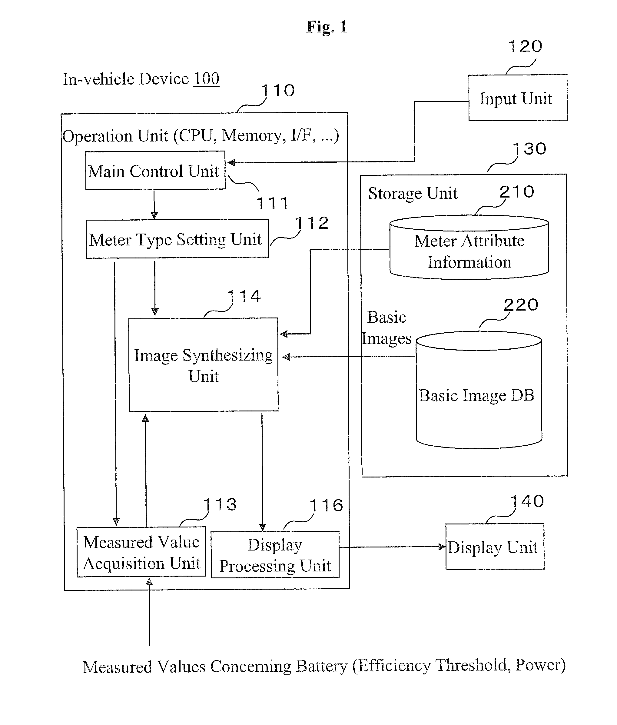
[0028]FIG. 1 is a schematic block diagram showing an in-vehicle device 100 according to an embodiment of the present invention.

[0029]As shown in FIG. 1, the in-vehicle device 100 comprises an operation unit 110; an input unit 120, a storage unit 130 and a disp...


PUM


Abstract

Disclosed is an in-vehicle device for displaying a meter image in real time, wherein the processing load is reduced without deterioration of the appearance of the meter image. The in-vehicle device stores therein a plurality of basic images which can indicate a first measured value and a second measured value both of which are measured values relating to the vehicle. According to the acquired first and second measured values, the in-vehicle device selects a predetermined basic image out of the plurality of basic images, transmits a partial area of the selected basic image, and synthesizes these basic images, to thereby generate a meter image to be displayed.

Description

TECHNICAL FIELD [0001]The present invention relates to an in-vehicle device.BACKGROUND ART [0002]Patent Document 1 discloses a technique of displaying a specific measured value on a screen of an image display unit provided in an in-vehicle device. Such an in-vehicle device generates a meter image by superimposing an image of an indicating needle (which indicates a measured value acquired through a sensor) upon an image imitating a dial of a mechanical meter, and displays the generated meter image on the image display unit. Then, to display the measured value in real time, the in-vehicle device repeats the rendering processing.[0003]Japanese Un-examined Patent Application Laid-Open No. 8-240447[0004]Henceforth, it is considered to decorate a meter image variously from the viewpoint of visibility and aesthetic appreciation. For example, it is possible to make a meter image look more attractive by superimposing a semi-transmissive graph (for example, a bar graph) indicating a measured ...

Claims


Application Information

Patent Timeline
IPC IPC(8): G06T11/40
CPCG01D7/00
Inventor NAGASHIMA, TAKANOBU
Owner CLARION CO LTD
Why Eureka
Try Eureka