Liquid ejecting apparatus

a liquid ejecting and apparatus technology, applied in the direction of printing, other printing apparatus, etc., can solve the problems of non-uniform distribution of risk of transportation failure, and heat applied to the surface of a recording target medium, so as to reduce the turbulence of airflow at the liquid ejecting head side, the effect of high precision

Active Publication Date: 2011-11-03
SEIKO EPSON CORP
View PDF5 Cites 41 Cited by
  • Summary
  • Abstract
  • Description
  • Claims
  • Application Information

AI Technical Summary

Benefits of technology

[0035]In such a preferred configuration, the air screen member substantially reduces the flow of warm air blown by the drying device toward the liquid ejecting head. Therefore, the turbulence of airflow at the liquid-ejecting-head side is reduced on the paper transportation path. Thus, it is possible to print an image on the recording target medium with high precision.

Problems solved by technology

For this reason, there is a risk of a transportation failure such as a paper jam.
In such a preferred configuration, heat applied to the surface of a recording target medium is in non-uniform distribution in the direction of the width thereof because of the presence of the plurality of roller body members provided on the rotating shaft at intervals in a shaft direction and regions between the roller body members.

Method used


Image

  • Liquid ejecting apparatus
  • Liquid ejecting apparatus
  • Liquid ejecting apparatus

Examples


first embodiment

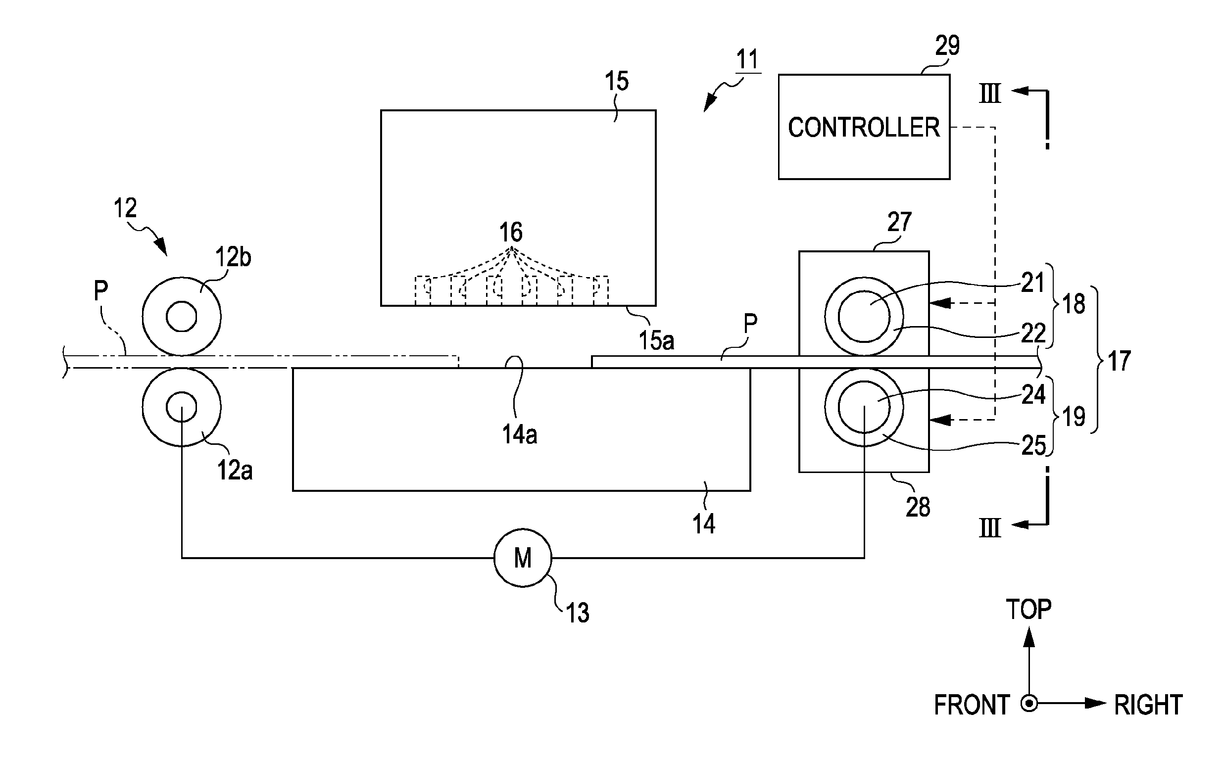
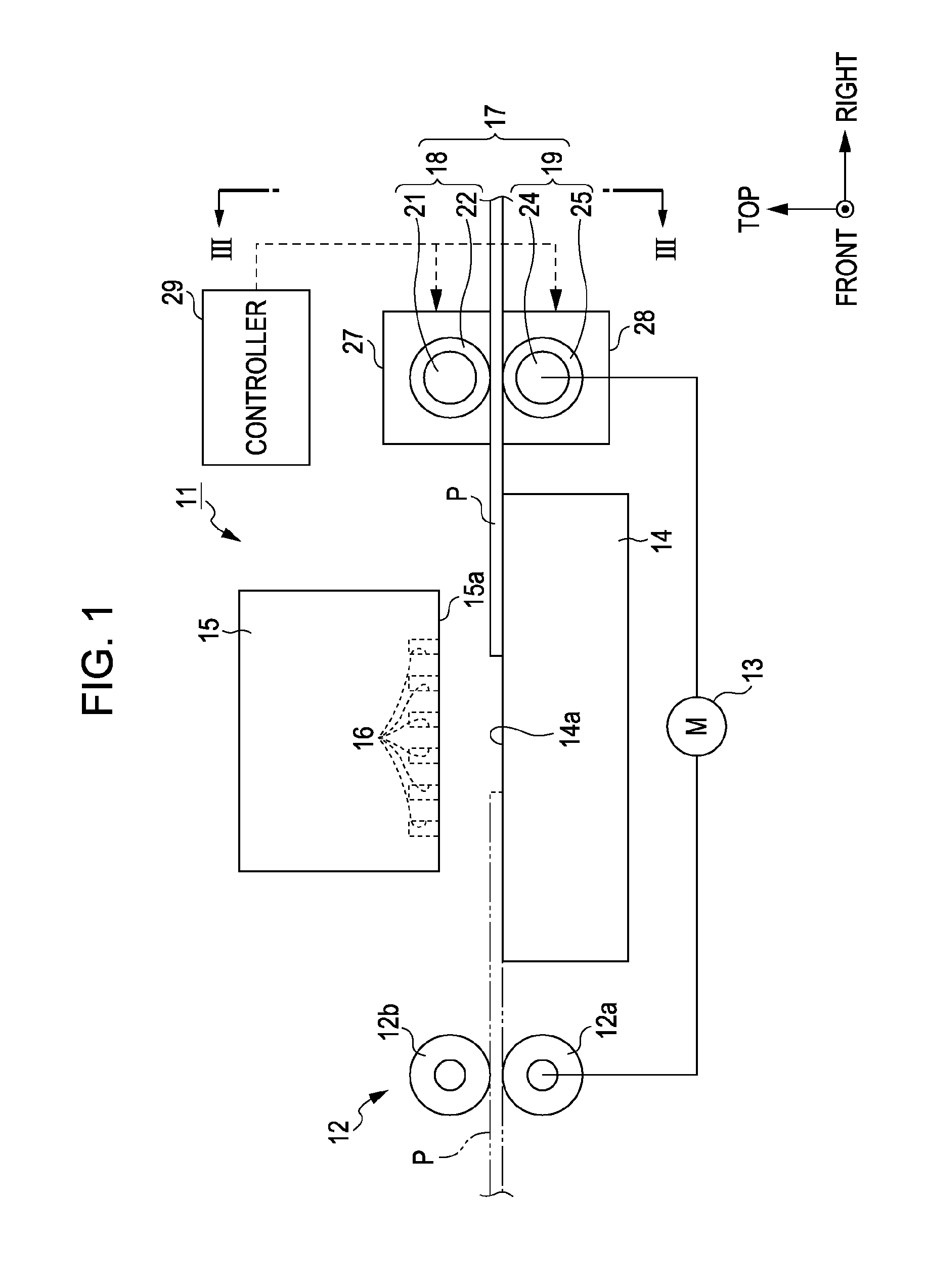
[0051]With reference to FIGS. 1 to 4, an ink-jet printer according to an exemplary embodiment of the invention will now be explained in detail. The ink-jet printer described below is a kind of a liquid ejecting apparatus according to an aspect of the invention. The term “forward / backward direction” that appears in the following description of this specification mean the “from-back-to-front” direction (or “from-front-to-back” direction when viewed in the reverse orientation) (front / back) (depth) shown by an arrow in each of the accompanying drawings unless otherwise specified. The terms “horizontal direction” and “vertical direction” that appear in the following description of this specification mean the leftward / rightward (left / right) direction and the upward / downward (top / bottom) direction shown by arrows in each of the accompanying drawings unless otherwise specified.

[0052]As illustrated in FIG. 1, an ink-jet printer 11, which is an example of a liquid ejecting apparatus, has a pa...

second embodiment

[0076]Next, with reference to FIGS. 5 and 6, a second embodiment of the present invention will now be explained. A major difference between the first embodiment of the invention and the second embodiment of the invention lies in a part of the structure of the heating roller unit 17. Except for the above difference, the structure of the second embodiment is substantially the same as that of the first embodiment. Therefore, the following description is focused on differences between the first embodiment of the invention and the second embodiment of the invention. Note that the same reference numerals are consistently used for components that are the same as those of a printer according to the first embodiment of the invention to avoid redundant explanation.

[0077]As illustrated in FIGS. 5 and 6, the heating roller unit 17 according to the present embodiment of the invention includes a heating driven roller 31 as a first roller and a heating driving roller 32 as a second roller. The fro...

third embodiment

[0097]With reference to FIGS. 7 to 10, a third embodiment of the present invention will now be explained. The term “forward / backward direction” that appears in the following description of this specification mean the “from-back-to-front” direction (or “from-front-to-back” direction when viewed in the reverse orientation) (front / back) (depth) shown by an arrow in each of the accompanying drawings unless otherwise specified. The terms “horizontal direction” and “vertical direction” that appear in the following description of this specification mean the leftward / rightward (left / right) direction and the upward / downward (top / bottom) direction shown by arrows in each of the accompanying drawings unless otherwise specified.

[0098]As illustrated in FIG. 7, a printer 111 is equipped with a transportation unit 112 for transporting the recording paper P, which is an example of a recording (print) target medium. The transportation unit 112 includes a platen 113. The platen 113 has the shape of a...


PUM


Abstract

A printer includes a heating roller unit that heats recording paper at a position downstream of a recording head, which is provided at an upstream position, in the direction of the transportation of the recording paper. The recording head ejects ink to the recording paper that is transported from an upstream side to a downstream side. The heating roller unit is disposed along the direction of the width of the recording paper, which intersects with the transportation direction thereof. The heating roller unit is divided into a plurality of areas in the width direction. Heat applied by first areas of the plurality of areas to the recording paper is different from heat applied by second areas, which are adjacent to the first areas in the width direction, to the recording paper.

Description

CROSS REFERENCE TO RELATED APPLICATIONS[0001]This application claims the benefit of Japanese Patent Application No: 2010-104922 filed Apr. 30, 2010 and 2010-107173 filed May 7, 2010, the contents of which are hereby incorporated by reference in their entirety.BACKGROUND[0002]1. Technical Field[0003]The present invention relates to a liquid ejecting apparatus.[0004]2. Related Art[0005]An ink-jet printer is well known as a kind of a liquid ejecting apparatus. An ink-jet printer ejects ink (liquid) supplied to a recording head (liquid ejecting head) through nozzles, which are formed in the recording head, onto a recording target medium such as paper, thereby printing an image thereon. Some of ink-jet printers are equipped with a heating means that applies heat to ink ejected for printing onto a recording target medium during the transportation of the recording target medium so as to dry it (for example, refer to JP-A-2004-276437). Another known ink-jet printer is equipped with a drying...

Claims


Application Information

Patent Timeline
Patent Type & Authority Applications(United States)
IPC IPC(8): B41J29/38B41J2/05
CPCB41J11/002B41J11/0005B41J13/02B41J11/0024B41J11/0022
Inventor OKAMOTO, KATSUMI
Owner SEIKO EPSON CORP
Why Eureka
Try Eureka