Film formation method capable of preventing fluctuation of ribbon

a film formation method and ribbon technology, applied in auxillary shaping apparatus, butter production, polarising elements, etc., can solve the problems of uniform edge portion of the ribbon and decrease of the film plainness,

Inactive Publication Date: 2002-05-02
FUJIFILM HLDG CORP +1
View PDF3 Cites 9 Cited by
  • Summary
  • Abstract
  • Description
  • Claims
  • Application Information

AI Technical Summary

Problems solved by technology

In that case, high vacuum force is generated to produce more air turbulence in both lateral sides, which causes nonuniformity in edge portions of the ribbon.
Thus, the plainness of th

Method used


Image

  • Film formation method capable of preventing fluctuation of ribbon
  • Film formation method capable of preventing fluctuation of ribbon
  • Film formation method capable of preventing fluctuation of ribbon

Examples


embodiment

[0106] [Embodiment]

[0107] (Experiment A)

[0108] In experiment A, the dope has the following composition.

[0109] cellulose triacetate (acetylation ratio of 60.2%)

1 17.58 parts by weight dichloromethane 65 parts by weight methanol 14 parts by weight m-butanol 1 part by weight triphenyl phosphate 1.6 parts by weight biphenyl diphenyl phosphate 0.8 part by weight colloidal silica 0.02 part by weight

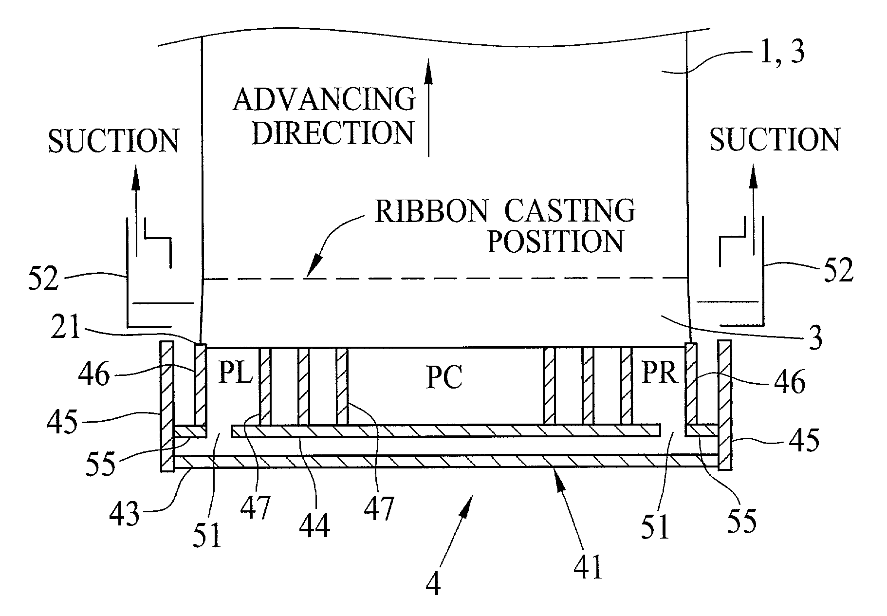
[0110] After preparing the dope from the above composition, plural films are formed by changing various conditions. A thickness T of the lateral end seal is 5 mm. A casting speed of the ribbon 3 is 50 m / min. The degree of decompression PC is -98.1 Pa (-10 mmAq). A thickness of the film is 80 .mu.m. Other formation parameters are shown in FIG. 8, in which comparison means a comparative embodiment, V1 represents the value (PC-PL).times.100 / .vertline.PC.vertline., V2 represents the value .vertline.PL-PR.vertline..times.100 / .vertline.0.5(PL+PR).vertline., {overscore (L)} is an average value of L. R...

experiment b

[0111] (Experiment B)

[0112] In experiment B, the dope has the following composition.

[0113] cellulose triacetate (acetylation ratio of 59.7%)

2 20.58 parts by weight methyl acetate 60 parts by weight acetone 8 parts by weight ethanol 10 parts by weight triphenyl phosphate 1.6 parts by weight biphenyl diphenyl phosphate 0.8 part by weight colloidal silica 0.02 part by weight

[0114] After preparing the dope from the above composition, a plurality of films are formed by changing various conditions. A thickness of the side seal T is 5 mm. A casting speed of the ribbon 3 is 50 m / min, and a degree of decompression PC is -343.2 Pa (-35 mmAq). A thickness of the film is 40 .mu.m. Other formation conditions are the same as those in Experiment A. R terraced unevenness value, appearance and result are shown in FIG. 10.

experiment c

[0115] (Experiment C, D)

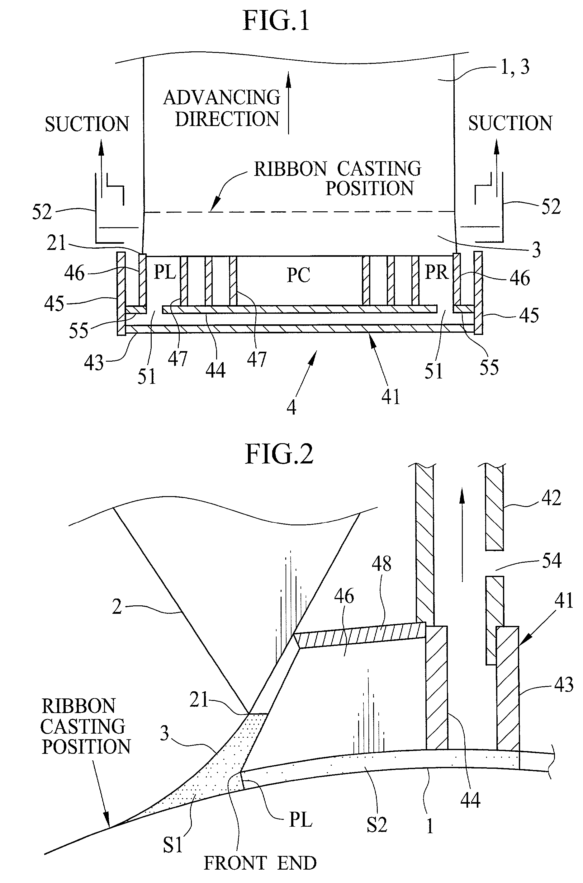
[0116] In Experiment C, the film is made from the dope used in Experiment A by use of a multiple flow cast die 65 of feedblock type shown in FIG. 7. In Experiment D, on the other hand, the film is made from the dope used in Experiment B by use of the multiple flow cast die 65. As shown in FIG. 11, the film 70 obtained in Experiment C, D includes an inner layer 71, a surface layer 72 and a back layer 73. A dry thickness of the inner layer 71 is 50 im. The amount of cellulose acetate of the dope for the surface and back layers 72, 73 is 5% smaller than that for the inner layer 71. A dry thickness of the surface and back layers 72, 73 is 5 mm. In Experiment C, D, a thickness of the side seal T is 5 mm. A casting speed of the ribbon 3 is 60 m / min, and a degree of decompression PC is -245.2 Pa (-25 mmAq). R terraced unevenness value, appearance and result are respectively shown in FIG. 12 (Experiment C) and FIG. 13 (Experiment D).

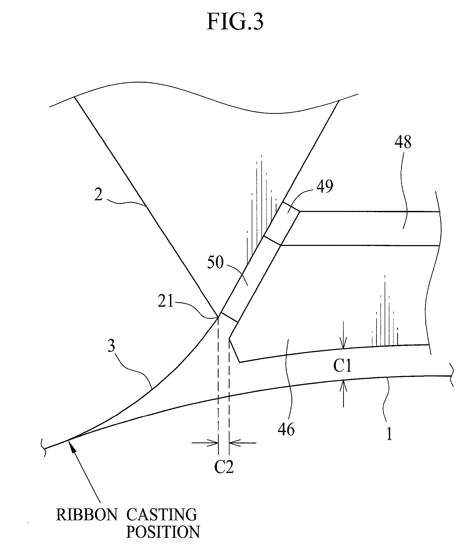
[0117] R terraced unevenness value...


PUM

PropertyMeasurementUnit
Lengthaaaaaaaaaa
Pressureaaaaaaaaaa
Lengthaaaaaaaaaa

Abstract

A film is formed by casting a ribbon on a support from a flow cast die while pulling said ribbon toward said support by providing a decompression area. The decompression area is divided into a middle portion, a left portion and a right portion. Degrees of decompression in these three portions satisfy the following formulae: <paragraph lvl="0"><in-line-formula>0<(PC-PL)x100/|PC|<15; </in-line-formula><paragraph lvl="0"><in-line-formula>0<(PC-PR)x100/|PC|<15; </in-line-formula><paragraph lvl="0"><in-line-formula>|PL-PR|x100/|0.5(PL+PR)|<10; </in-line-formula>wherein PC is a degree of decompression in said middle portion, PL a degree of decompression in said left portion, and PR a degree of decompression in said right portion. The film obtained by the above method is suitable for a polarizing plate protection film, which is used for a liquid crystal display device.

Description

[0001] 1. Field of the Invention[0002] The present invention relates to a film formation method for casting a ribbon including polymer solution on a support from an extruder die. More specifically, the present invention relates to a film forming method in which the ribbon is cast on the support without fluctuation.[0003] 2. Background Arts[0004] A cellulose triacetate film can be used as a support for a photosensitive material. The cellulose triacetate film is formed by a liquid film formation method, in which a filmy polymer solution in an organic solvent is cast onto the moving support from an extruder die. The filmy polymer solution ranged from a nozzle of the extruder die to the support is called as ribbon. In order to fix the ribbon on the support and to prevent introduction of the air into the polymer solution, JP-A 2-52721, JP-A 6-155494 and JP-A 10-264185 disclose a film forming method in which a decompression area is formed behind the extruder die by a decompression device....

Claims


Application Information

Patent Timeline
IPC IPC(8): B29C41/26B29C41/28G02B5/30B29C41/32B29C41/36B29C41/52C08J5/18C08K3/00C08K5/00C08L1/12
CPCB29C41/26
Inventor YAMAZAKI, HIDEKAZUKATAI, YUKIHIRONAKAMURA, TOSHIKAZU
Owner FUJIFILM HLDG CORP
Why Eureka
Try Eureka