
Image capturing apparatus

a technology of image capturing and capturing apparatus, which is applied in the field of image capturing apparatus, can solve the problems of inconvenient high-speed focus adjustment operation, large apparatus, and inability to operate during live view, and achieve the effect of suppressing the deterioration of image quality

Active Publication Date: 2011-11-03
CANON KK
View PDF5 Cites 44 Cited by
  • Summary
  • Abstract
  • Description
  • Claims
  • Application Information

AI Technical Summary

Benefits of technology

The present invention is about improving image quality in an image capturing apparatus that has focus detection pixels. It addresses the problem of deteriorated image quality caused by focus detection pixels when thinning and reading out a pixel signal. The invention includes an image sensor with discretely arranged focus detection pixels, a focus adjusting means, a readout means with two thinning and readout modes, and a selecting means to select the appropriate mode based on the image capturing apparatus state. The technical effect of the invention is to improve image quality by reducing the impact of focus detection pixels on image quality.

Problems solved by technology

However, because an evaluation value is determined while moving the imaging lens in small amounts, and because it is necessary to move the lens until an evaluation value is determined with certainty to be the maximum, this method is not suitable for high-speed focus adjustment operation, and is also called a mountain-climbing method.
For this reason, there is the disadvantage that the apparatus becomes large and expensive.
There is also the disadvantage that operation cannot be done during live view since the quick-return mirror is retreated.
However, because image information is created by interpolation from surrounding imaging pixels at locations at which focus detection pixels are arranged and that are defective portions of the imaging pixels in the aforementioned Japanese Patent Laid-Open No. 2000-156823 and Japanese Patent Laid-Open No. 2000-292686, there are cases in which interpolation cannot be done properly, depending on the object.
For this reason, although the deterioration in image quality is small in the case that the number of focus detection pixels is small compared to the number of normal imaging pixels, there is the problem that the deterioration in image quality becomes large with the increase in the proportion of focus detection pixels.
However, when pixel arrangement is done such that focus detection pixels are included in the read out pixel signal, the proportion of focus detection pixels with respect to imaging pixels increases in comparison to a case in which all pixels are read, and the effect on image quality becomes large.
However, Japanese Patent Laid-Open No. 2000-156823 has the problem that because the focus detection pixels are not read out when a portion of the pixels of the image sensor are thinned out and read out at high speed, auto focus adjustment cannot be executed while executing live view.

Method used


Image

  • Image capturing apparatus
  • Image capturing apparatus
  • Image capturing apparatus

Examples


Embodiment Construction

[0028]Hereinafter, an embodiment of the present invention will be explained in detail with reference to the drawings.

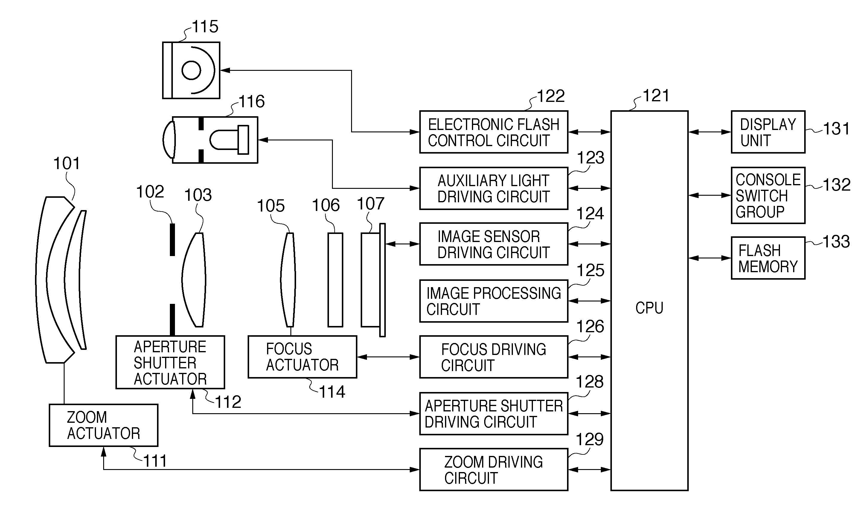
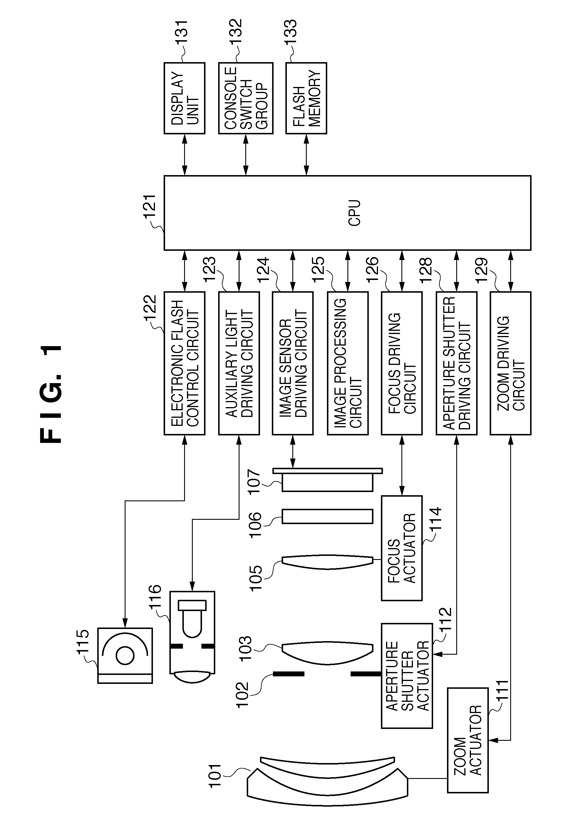
[0029]FIG. 1 is a structural diagram of a camera as an image capturing device according to an embodiment of the present invention, and illustrates a digital camera in which a camera main body that has an image sensor and an imaging lens are combined as a unit. In FIG. 1, reference numeral 101 is a first lens group arranged at the end of an imaging optical system (image forming optical system), and is held to be movable in the direction of the light axis. Reference numeral 102 is a dual-purpose aperture and shutter, and in addition to executing adjustment of the amount of light during image capture by adjusting the diameter of the opening thereof, moves as a shutter for adjustment of the exposure time during still image capture. Reference numeral 103 is a second lens group. The dual-purpose aperture and shutter 102 and second lens group 103 move as a unit in the direct...


PUM


Abstract

An image capturing apparatus is provided with an image sensor that has a first pixel group and a second pixel group, a focus adjustment unit that executes focus adjustment of an imaging lens based on the signal from the second pixel group, a readout unit that has a first thinning and readout mode that thins and reads out signals from the plurality of pixels at a predetermined thinning ratio and thinning phase, and a second thinning and readout mode that thins and reads out signals from the plurality of pixels with a difference in at least one of the thinning ratio and the thinning phase from the first thinning and readout mode, and a selecting unit that selects in which mode to operate the readout means from among the first and second thinning and readout modes in accordance with the state of the image capturing apparatus.

Description

TECHNICAL FIELD[0001]The present invention relates to a control technique for reading out a pixel signal of an image capturing apparatus that has a focus detection pixel in a portion of the image sensor.BACKGROUND ART[0002]Some current image capturing devices that have a solid-state image sensor such as a CCD or CMOS sensor have a live view function. A live view function is a function that allows confirmation of an object image by sequentially outputting an image signal that is continuously read out from an image sensor onto a display device such as a liquid crystal display or the like arranged on the rear surface or elsewhere on a camera. Also, as a common method of using a light beam that passes through an imaging lens in an auto focus detection / adjustment method of an image capturing device, there is a contrast detection method (called a blur method) and a phase difference detection method (called a deviance method).[0003]The contrast detection method is a method that is often us...

Claims


Application Information

Patent Timeline
Patent Type & Authority Applications(United States)
IPC IPC(8): G03B13/00H04N25/00G02B7/28G02B7/34G03B13/36H04N23/12H04N25/42
CPCH04N5/23212H04N9/045H04N5/3458H04N5/343H04N23/672H04N25/42H04N25/704H04N25/447H04N23/843H04N25/134
Inventor HIROSE, MINORU
Owner CANON KK
Learn More