Stimulation of penis erection

Active Publication Date: 2011-11-03
FORSELL PETER
5 Cites 18 Cited by

AI-Extracted Technical Summary

Problems solved by technology

This will greatly improve the patient's comfort as he no longer needs to pier...

Benefits of technology

[0007]The essence of the invention lies in injecting a substance for stimulating penis erection into the patient's body using an implantable infusion device. More specifically, in order to stimulate penis erection the substance may be injected into both the right and left corpus cavernosum and/or into the two deep arteries thereof and/or possibly into muscle tissue regulating blood flow through the right and left corpus cavernosum and/or into tissue in close proximity to the left and right corpus cavernosum, by means of an infusion device permanently implanted at an appropriate location inside the patient's body. This will greatly improve the patient's...

Abstract

A penis erection stimulation system comprises an infusion device (11) adapted for implantation inside the patient's body and at least one reservoir (R1, R2) adapted for implantation inside the patient's body in fluid connection with the infusion device to supply to the infusion device a substance to be injected into the patient's body. The reservoir comprises at least one first compartment accommodating or adapted to accommodate a first substance and at least one second compartment accommodating or adapted to accommodate a second substance, said second substance being a drug for stimulating penis erection. The infusion device preferably comprises one or more infusion needles disposed within and implanted along with one or more housings adjacent the patient's left and right corpora cavernosa. A pump may be implanted inside the patient's body to supply the infusion needle with infusion liquid. A drive unit also adapted for implantation inside the patient's body may be arranged for advancing and retracting the tip end of the infusion needle such that it penetrates the housing at least in two different penetration areas either simultaneously or in immediate time succession, thereby injecting drugs along with the infusion liquid into the patient's body for stimulating penis erection.

Application Domain

Technology Topic

Image

  • Stimulation of penis erection
  • Stimulation of penis erection
  • Stimulation of penis erection

Examples

  • Experimental program(9)

Example

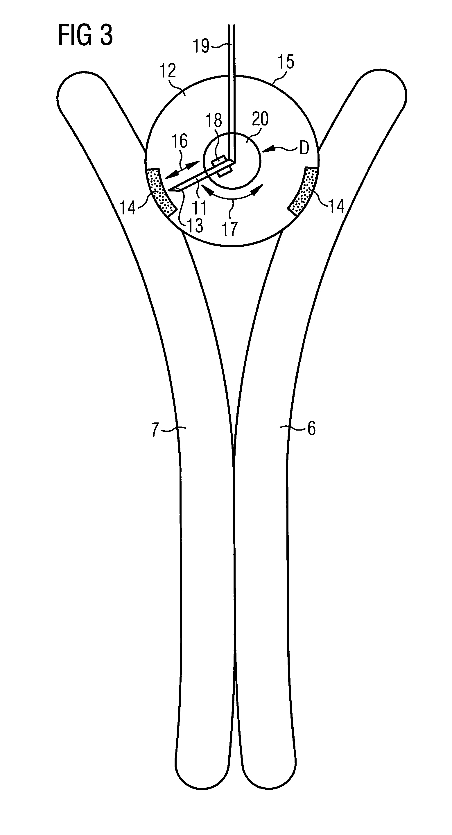
[0121]FIG. 5 shows a third embodiment which differs from the first and second embodiments in that it comprises two infusion needles 11 contained in the housing 15. Thus, when infusion liquid is guided through the conduit 19 towards the two infusion needles 11, both needles are advanced and retracted simultaneously along the direction 16, so that injection of infusion liquid occurs at exactly the same time. The drive unit D or a separate drive unit may be used to turn the turntable 20 on which the infusion needles 11 are mounted, stepwise in the direction 17 so that the window areas 14 will be penetrated by the tip end of the infusion needle 11 at different penetration sites during the next following injection cycle. Again, one or more motors M, not shown in FIG. 5, may be used for driving one or more of the components of the drive unit D.
[0122]The principle of a guide structure for laterally displacing the infusion needle will now be described in context with FIG. 6. Such guide structure may be used e.g. for each of the two infusion needles 11 shown in FIG. 5 or may also be used slightly modified for the lateral displacement of the infusion needle 11 shown in FIGS. 3 and 4.
[0123]The guide structure 28 is securely fixed adjacent the self-sealing window area 14 which itself is implanted adjacent the patient's corpus cavernosum 7. The guide structure 28 comprises a guide pin 27 securely connected to the infusion needle 11 (not shown) such that the infusion needle 11 cooperates with the guide structure 28. Upon advancement or retraction of the infusion needle 11, the guide pin 27 will be guided in the guide structure 28 and thereby laterally displace the infusion needle 11, which lateral displacement causes rotation of the turntable 20 (not shown in FIG. 6). Resilient flaps 28a, 28b within the guide structure 28 serve to guide the guide pin 27 through the entire guide structure 28 upon repeated advancement and retraction of the infusion needle 11. The guide structure 28 is designed to provide different penetration sites through the self-sealing window area 14 into the corpus cavernosum 7. Where it is desired, the trajectory of guide structure 28 may include a return path 28c for the guide pin 27 to return to its starting position shown in FIG. 6. Such return action will be caused by a return spring 29 which is permanently fixed to a rigid part of the housing 15.
[0124]The same structure can likewise be used in the embodiments shown in FIGS. 3 and 4 to displace the single infusion needle 11 laterally between the two window areas 14. Of course, the structure would have to be slightly adapted to accommodate for the larger distance to be overcome between the two window areas 14.
[0125]FIG. 7 shows a preferred embodiment of a penetration membrane to be used as the self-sealing window area 14 in the outer wall 15 of the housing 12. The penetration membrane 30 is made from a composite material. The same material can also be used for other flexible wall portions or for an infusion port that will be described below in connection with another embodiment. The composite material of penetration membrane 30 shown in FIG. 7 comprises an outer shape-giving layer 30a defining a volume in which a self-sealing soft material 30b is contained. Self-sealing soft material 30b can be of gel type having a viscosity such that it does not flow through any penetrations caused by the infusion needle 11 during penetration of the outer shape-giving layer 30a. Instead of a single outer shape-giving layer 30a, the shape-giving layer 30a may comprise a plurality of layers. The outer shape-giving layer 30a preferably comprises silicone and/or polyurethane, since such materials can be produced to have self-sealing properties in respect of penetrations resulting from the infusion needle 11.
[0126]Instead of a self-sealing membrane, the window area 14 in the outer wall 15 of the housing 12 may be formed by one or more flaps, as shown in FIG. 8. Two flaps 30′ being made from a resilient, biocompatible material are arranged so as to form a slit which is normally closed and through which the infusion needle 11 can pass when it is advanced. Upon advancement of the infusion needle 11, the needle will push aside the normally closed flaps 30′, and when the needle 11 is retracted again, the flaps 30′ will return to their normally closed position so as to form a seal against ingression of body liquid.
[0127]FIG. 9 shows a different embodiment. In this case, the self-sealing window 14 in the outer wall 15 comprises a door 30″ which can be opened by mechanical action. In the embodiment shown, the door is formed by a flap made from a resilient, biocompatible material which keeps the window area 14 closed in its normal position. A pull wire 300 is attached to one end of the door 30″ in order to allow for opening the door by pulling the pull wire 300. The pull wire 300 or any other drive connected to the door 30″ forms part of the drive unit coupled to the infusion needle 11. For instance, as is shown in FIG. 10, the pull wire 300 may be attached directly to the infusion needle 11 so that advancement of the infusion needle 11 will simultaneously cause the door 30″ to be lifted up so that the infusion needle 11 can pass underneath the door 30″ and thus penetrate the outer wall 15 easily. Due to the resiliency of the door material, the door 30″ will automatically close when the force, such as the pulling force exerted via the pull wire 300, is released. Instead or in addition, the closing action may be supported by at least one spring element urging the door into its closed position.

Example

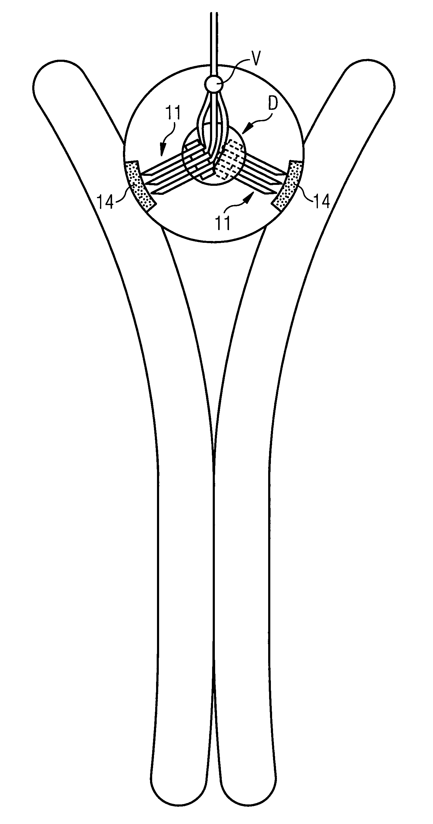
[0128]FIG. 11 shows a fourth embodiment comprising a plurality of infusion needles for each of the two window areas 14. In this embodiment it is not necessary to provide a turntable by which the needles can be pivoted stepwise in order to laterally displace the needles from one penetration site to a different penetration site within the same window area 14. Instead, upon successive injection cycles a different one of the plurality of injection needles will be advanced and retracted for each of the two window areas 14. Thus, the effect achieved is the same as in the embodiment shown in FIG. 5. However, instead of the turntable 20 (FIG. 5) a valve V is needed to direct the infusion liquid to only one of the plurality of infusion needles 11 in each of the two window areas 14. More specifically, depending upon the position of the valve V, a first one of the infusion needles 11 in the first window area 14 and a first one of the plurality of the infusion needles 11 in the second window area 14 will be advanced and retracted simultaneously, and during the next following infusion cycle, another one of the plurality of infusion needles will be advanced and retracted in the two window areas 14.

Example

[0129]FIG. 12 shows a fifth embodiment which differs from the first and second embodiments shown in FIGS. 3 and 4 in that the single infusion needle 11 is not only laterally displaceable in the direction 17 between the two window areas 14 but also laterally displaceable between different penetration sites 21 within the same penetration area 14. More specifically, the direction of lateral displacement of the tip end of the infusion needle 11 within each of said different penetration areas 14 is perpendicular to the direction of lateral displacement between the different penetration areas 14. To achieve this result, the drive unit D is configured to longitudinally advance and retract the infusion needle 11 along a direction 16, to pivot the infusion needle 11 by means of a turntable 20 between the two penetration areas 14 along a pivoting direction 17 and to raise or lower the infusion needle 11 along a third direction 22 perpendicular to the longitudinal direction 16. A suitable purely mechanical construction may perform this function. However, one or more motors may also be provided to perform one and/or the other of these functions.

PUM

no PUM

Description & Claims & Application Information

We can also present the details of the Description, Claims and Application information to help users get a comprehensive understanding of the technical details of the patent, such as background art, summary of invention, brief description of drawings, description of embodiments, and other original content. On the other hand, users can also determine the specific scope of protection of the technology through the list of claims; as well as understand the changes in the life cycle of the technology with the presentation of the patent timeline. Login to view more.

Similar technology patents

Classification and recommendation of technical efficacy words

  • Improve comfort
  • Convenient for patient

Treatment of teeth by aligners

InactiveUS20060275731A1Improve comfortReduce treatment time and costImpression capsAdditive manufacturing apparatusDental treatmentsOrthodontics
Owner:ALIGN TECH

Fan

Owner:UNIVERSAL SAFETY RESPONSE +1

Cleaning method and device for indoor heat exchanger of air conditioner

ActiveCN104848738AAchieve high temperature sterilization functionImprove comfortCleaning heat-transfer devicesSpace heating and ventilation safety systemsFrostEngineering
Owner:GREE ELECTRIC APPLIANCES INC
Why Eureka
Try Eureka