
Hoist rope equaliser

Active Publication Date: 2011-11-10
BRADKEN RESOURCES
View PDF18 Cites 3 Cited by
  • Summary
  • Abstract
  • Description
  • Claims
  • Application Information

AI Technical Summary

Benefits of technology

[0010]Embodiments of the invention can have a very limited vertical dimension. The advantage of the overall height of the load equaliser being small permits the lifting of the bucket higher than otherwise, thereby giving the distinct economic advantage of a higher discharge position. It has been found that an embodiment can offer a higher dumping level for a typical dragline of 1 metre and furthermore the load equaliser can have a dramatic reduction in mass compared with prior art proposals typically of the order of 1 tonne, thereby permitting a greater mass of overburden to be carried in the bucket for a particular rated dragline structure.
[0011]Embodiments lend themselves to providing a lubricated rotatable mounting thereby permitting a relatively long-life and reduction in downtime for inspection, servicing and replacement. The reduction in size of the product also facilitates not only reduced weight by also reduced cost for the components required. The components, for example, may be steel or any other suitable material.
[0013]Embodiments can offer the advantage of two degrees of freedom by the equaliser body having an upper component adapted to be engaged in the rotatable mounting and having a lower portion for a second rotatable mounting, about an axis at right angles to the first rotatable mounting of the equaliser system, and thus providing a further degree of freedom for rotation of a component to be engaged with flexible coupling elements (such as chains) to the bucket structure.

Problems solved by technology

However, long working life particularly and readily replaceable components are important.

Method used


Image

  • Hoist rope equaliser
  • Hoist rope equaliser
  • Hoist rope equaliser

Examples


first embodiment

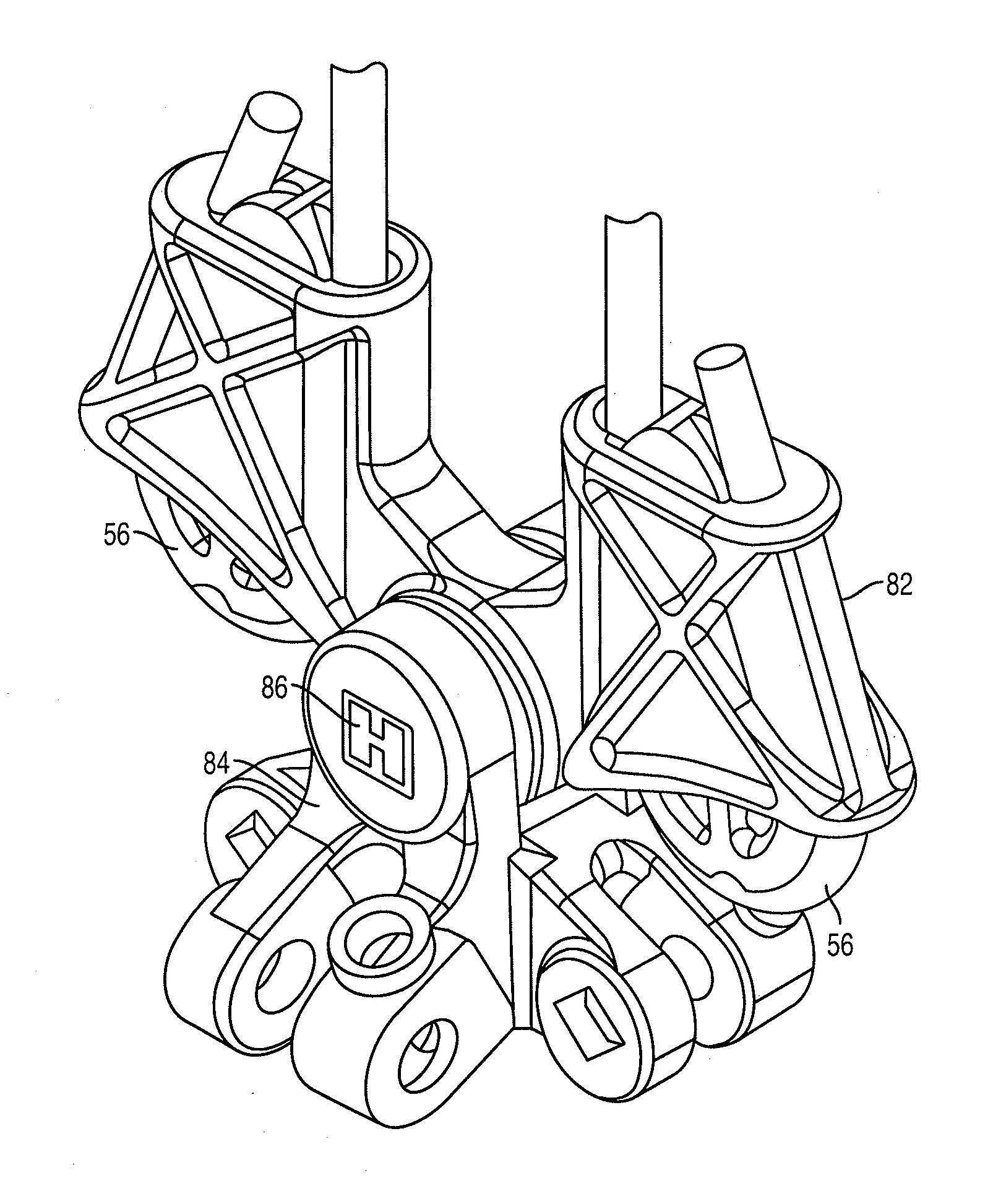
[0053]FIG. 8-12 illustrates the present invention, comprising of a tri-link 84 connected to an integrated socket equaliser 82 by a connector pin 86, and a pair of locking wedges 56. The locking wedges 56 operate in the same manner to the prior art to secure the hoist ropes 58.

[0054]FIG. 9 shows in perspective the first embodiment where it is apparent the tri-link 84 has one degree of freedom of motion relative to the integrated socket equaliser body 82. This arrangement allows the tri-link 84 to have limited rotation from central alignment, while equalising the load on the hoist chains 16.

[0055]FIG. 12 shows the connector pin 86 extending longitudinally of the apparatus to allow load equalisation and rotation around the longitudinal axis.

[0056]A more detailed description of the separate sub-components of the first embodiment will now be given.

[0057]FIG. 8 is an exploded drawing of the first embodiment of the present invention, showing an integrated socket equaliser 82 comprising two...

third embodiment

[0065]A more detailed description of the separate sub-components of the third embodiment will now be given.

[0066]FIG. 18 is an exploded drawing of the third embodiment of the present invention. The integrated socket equaliser 94 comprises two integrated hoist rope clamps 87 extending laterally from the body, joined by a central web 88, and a central ball socket 102 located on the central web 88. The hoist rope clamps 87 are similar to those described in the first embodiment. The tri-link 96 is substantially similar to the tri-link 84 in the first embodiment, except for the elongated pair of links 92.

[0067]As illustrated in FIG. 23, the spherical bearing 98 is mounted centrally in the ball socket 102, and retained by a pair of bearing race 100 also mounted in the ball socket 102. The bearing race 100 is in the form of a ring, where the interior surface 103 is profiled to match the spherical surface 104 of the spherical bearing 98. This relationship enables the spherical bearing 98 to...


PUM


Abstract

A load equaliser for supporting a drag line bucket from first and second cables is disclosed. The load equalizer has a main body having a central portion and side portions providing respectively first and second clamps for clamping end portions of the first and second suspension cables. A rotatable mounting is provided in the suspension central portion of the main body. A link body is suspended below the main body and connected thereto through the rotatable mounting whereby freedom of relative rotational motion is provided at least about an axis substantially at right angles to the direction between the clamps. The rotatable mounting is in a zone extending substantially between the clamps.

Description

BACKGROUND OF THE INVENTION[0001]The present invention relates to a hoist rope equaliser and is more particularly directed to a system in which an object is to be suspended and moved in a system having a plurality of hoist ropes which connect to the equaliser and the equaliser has a plurality of flexible connection elements such as chains on which the object is mounted. The equaliser has a structure such that load on the respective flexible elements is equalised and the line of action preserved along the direction of elongation of each of the support cables. A particular application of the invention but not necessarily its only application is to a system for use with a dragline having a rigging system which supports and operates a dragline bucket.[0002]Dragline excavators are frequently used to remove overburden to prepare an open-cut coalmining operation. A bucket is provided and capable of scooping a large volume of soil. The bucket is suspended off a long boom with support cables...

Claims


Application Information

Patent Timeline
IPC IPC(8): B66D1/50B66D1/40
CPCB66C3/125
Inventor ATTWOOD, REECE
Owner BRADKEN RESOURCES
Features
  • Generate Ideas
  • Intellectual Property
  • Life Sciences
  • Materials
  • Tech Scout
  • Unparalleled Data Quality
  • Higher Quality Content
  • 60% Fewer Hallucinations
Learn More