Feedforward controlled envelope modulator and feedforward control circuit thereof

a control circuit and envelope modulator technology, applied in the field of polar transmitters, can solve the problems of low power efficiency, large amount of total power consumption in transmission links, and bias drift in handheld communication devices, and achieve the effects of improving the efficiency of polar transmitters, saving battery energy, and stable output curren

Active Publication Date: 2011-11-10
IND TECH RES INST
View PDF0 Cites 25 Cited by
  • Summary
  • Abstract
  • Description
  • Claims
  • Application Information

AI Technical Summary

Benefits of technology

The invention uses a special feedback system called feedforward control to make sure that both the linear amplifier and the switch amp are always producing consistent levels of output current. This results in more efficient use of power which means less drain on the battery used for powering the device's communication functions.

Problems solved by technology

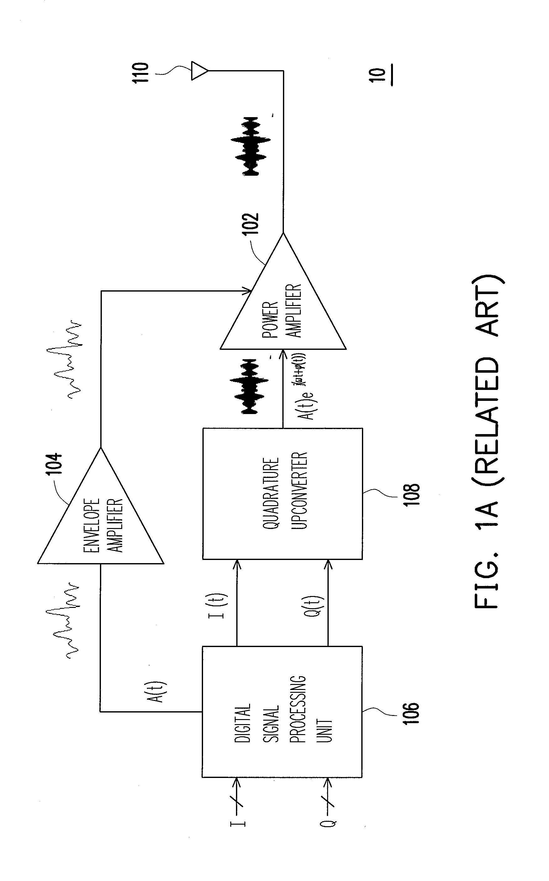
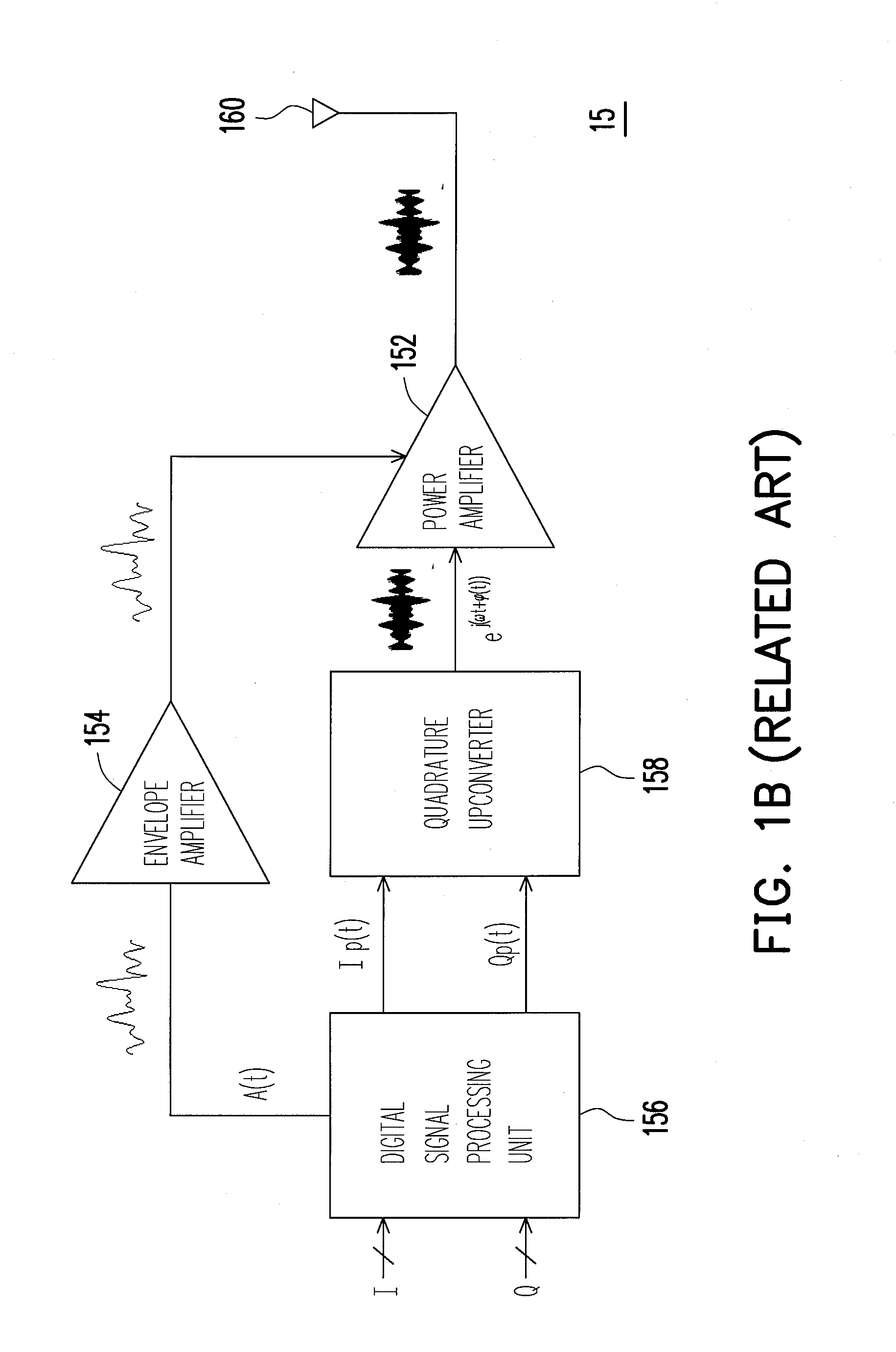
The technical problem addressed in this patent text is the low power efficiency of the power amplifier in handheld communication devices, which results in reduced battery life and increased temperature. The patent proposes a polar power amplifier that combines high linearity and high power efficiency to solve this problem. The polar transmitter uses a polar power amplifier that has ET or EER function, depending on the required performance requirements. The envelope amplifier in the polar transmitter can be implemented by a linear regulator, a switching regulator, or a current feedback hybrid envelope modulator, with each having its own advantages and disadvantages. The current sensing resistor must be small to reduce power consumption, but this can result in power inefficiency and difficulty in implementing in integrated circuit design.

Method used


Image

  • Feedforward controlled envelope modulator and feedforward control circuit thereof
  • Feedforward controlled envelope modulator and feedforward control circuit thereof
  • Feedforward controlled envelope modulator and feedforward control circuit thereof

Examples


Embodiment Construction

[0030]Exemplary embodiments are described more fully hereinafter with reference to the accompanying drawings. Exemplary embodiments may, however, be in many different forms and should not be construed as limited to the exemplary embodiments set forth herein. Rather, these exemplary embodiments are provided so that this disclosure will be thorough and complete, and will fully convey the scope to those skilled in the art. In the drawings, the size and relative sizes of components may be exaggerated for clarity. Throughout the drawings, like reference numerals refer to like components.

[0031]It will be understood that, although the terms first, second, third, etc. may be used herein to describe various elements, components, regions, layers and / or sections, these elements, components, regions, layers and / or sections should not be limited by these terms. These terms are only used to distinguish one element, component, region, layer or section from another element, component, region, layer...


PUM


Abstract

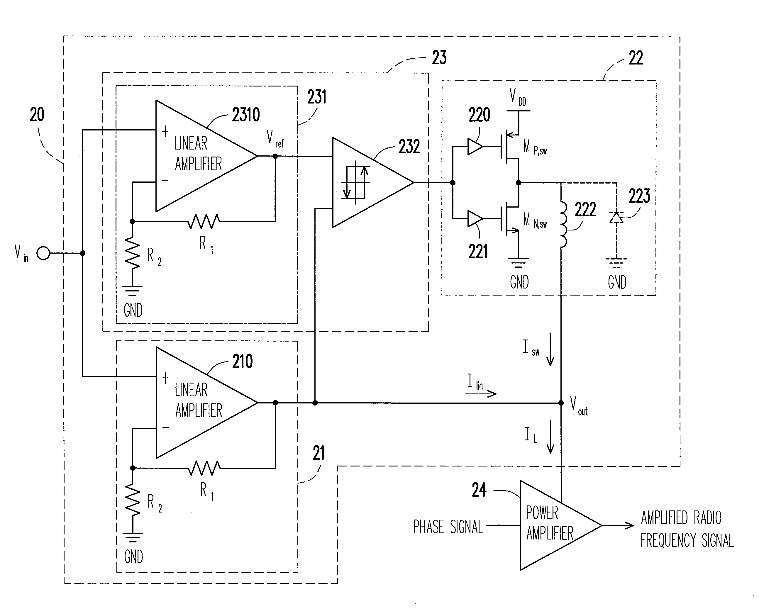
The present disclosure illustrates a feedforward controlled envelope modulator and a feedforward control circuit thereof. The feedforward controlled envelope modulator comprises a linear amplifier circuit, a switching amplifier, and a feedforward control circuit. The linear amplifier circuit amplifies an input voltage signal, so as to output an output voltage signal to a load node. The switching amplifier receives a comparison signal, and outputs a switching current to the load node according to the comparison signal. The feedforward control circuit comprises a duplicate linear amplifier circuit and a hysteresis comparator. The duplicate linear amplifier circuit amplifies the input voltage signal, so as to output a reference voltage signal, wherein an amplifying gain of the duplicate linear amplifier circuit is identical to an amplifying gain of the linear amplifier circuit. The hysteresis comparator compares the output voltage signal and the reference voltage signal, so as to output the comparison signal.

Description


Claims


Application Information

Patent Timeline
Owner IND TECH RES INST
Why Eureka
Try Eureka