Multicore fiber transmission systems and methods

a transmission system and fiber technology, applied in multiplex communication, instruments, cladded optical fibres, etc., can solve the problem that the capacity per fiber has reached the limit of optical networks

Active Publication Date: 2011-11-10
OFS FITEL LLC
View PDF9 Cites 183 Cited by
  • Summary
  • Abstract
  • Description
  • Claims
  • Application Information

AI Technical Summary

Problems solved by technology

Recent information-theoretic studies have shown that capacity per fiber has reached the limiting point in optical networks.
Critical issues that will have a significant impact on the system performance and cost-effectiveness of MCF in practical applications include: (1) the development of structures and techniques for coupling individual signals from transceivers into and out of an MCF; (2) design and demonstration of efficient MCF which allows signal transport within each core with low loss and low crosstalk over long length; and (3) the development of MCF transmission systems that are capable of using commercially available components as transceivers at low cost with high cable density.

Method used


Image

  • Multicore fiber transmission systems and methods
  • Multicore fiber transmission systems and methods
  • Multicore fiber transmission systems and methods

Examples


Embodiment Construction

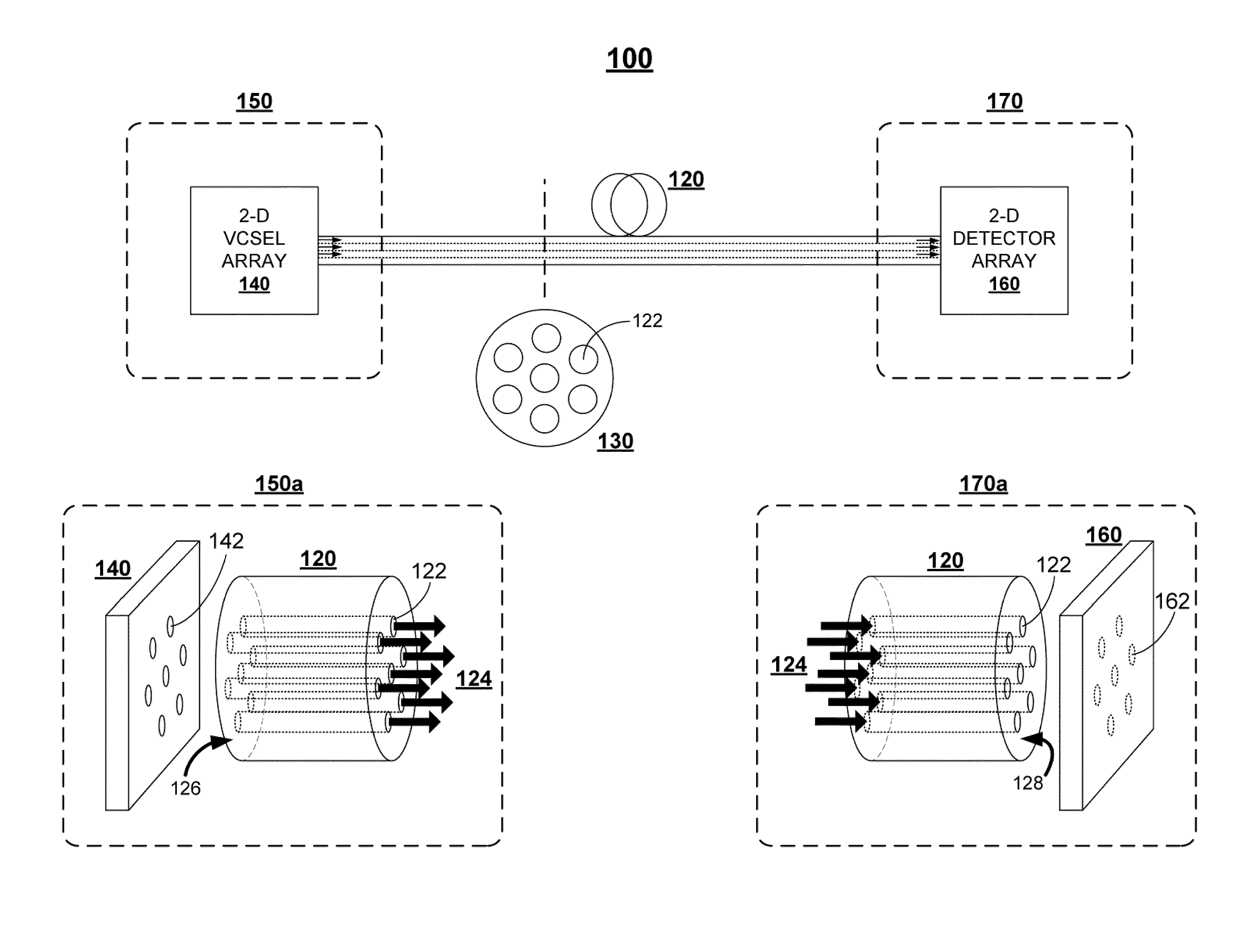
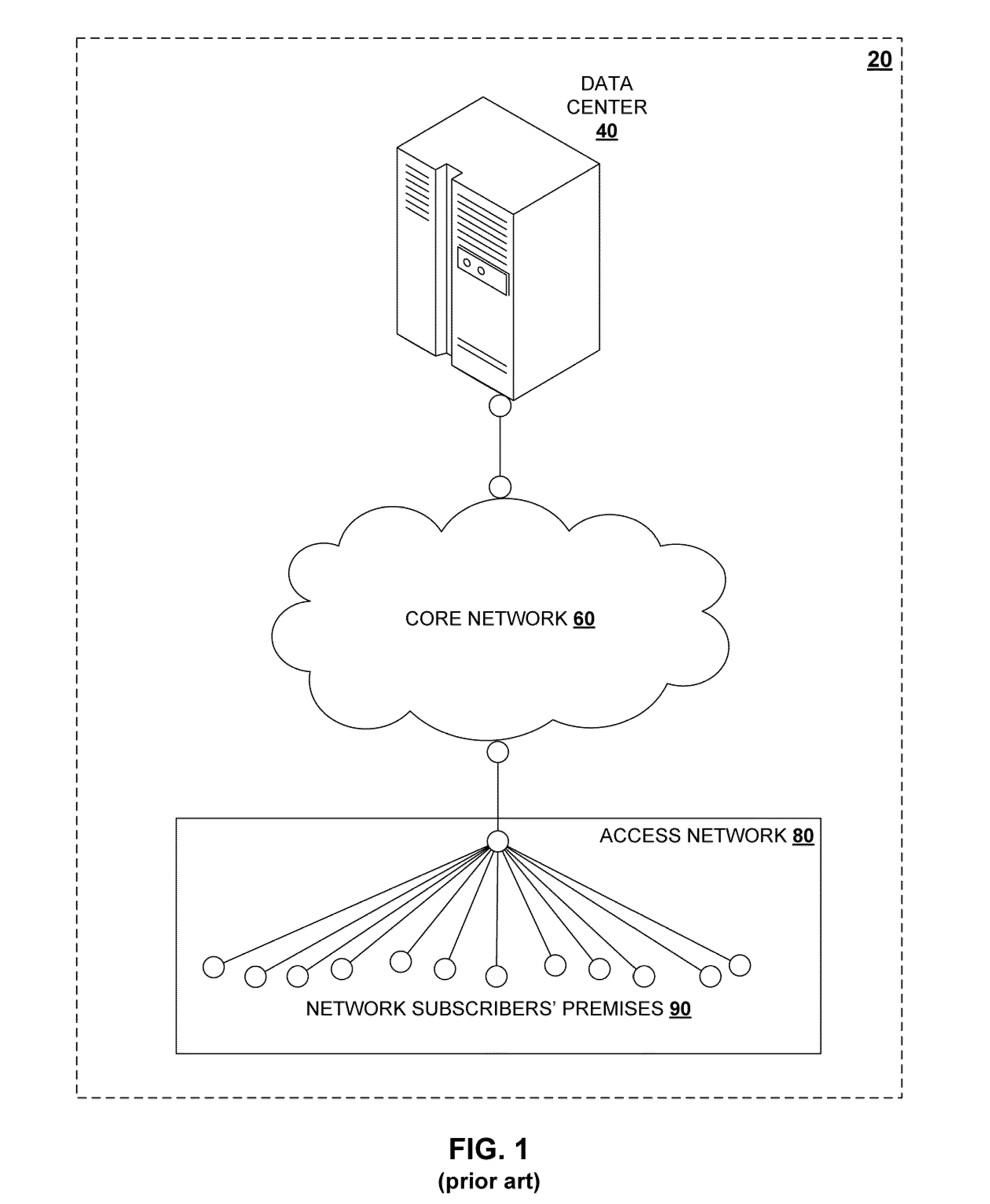
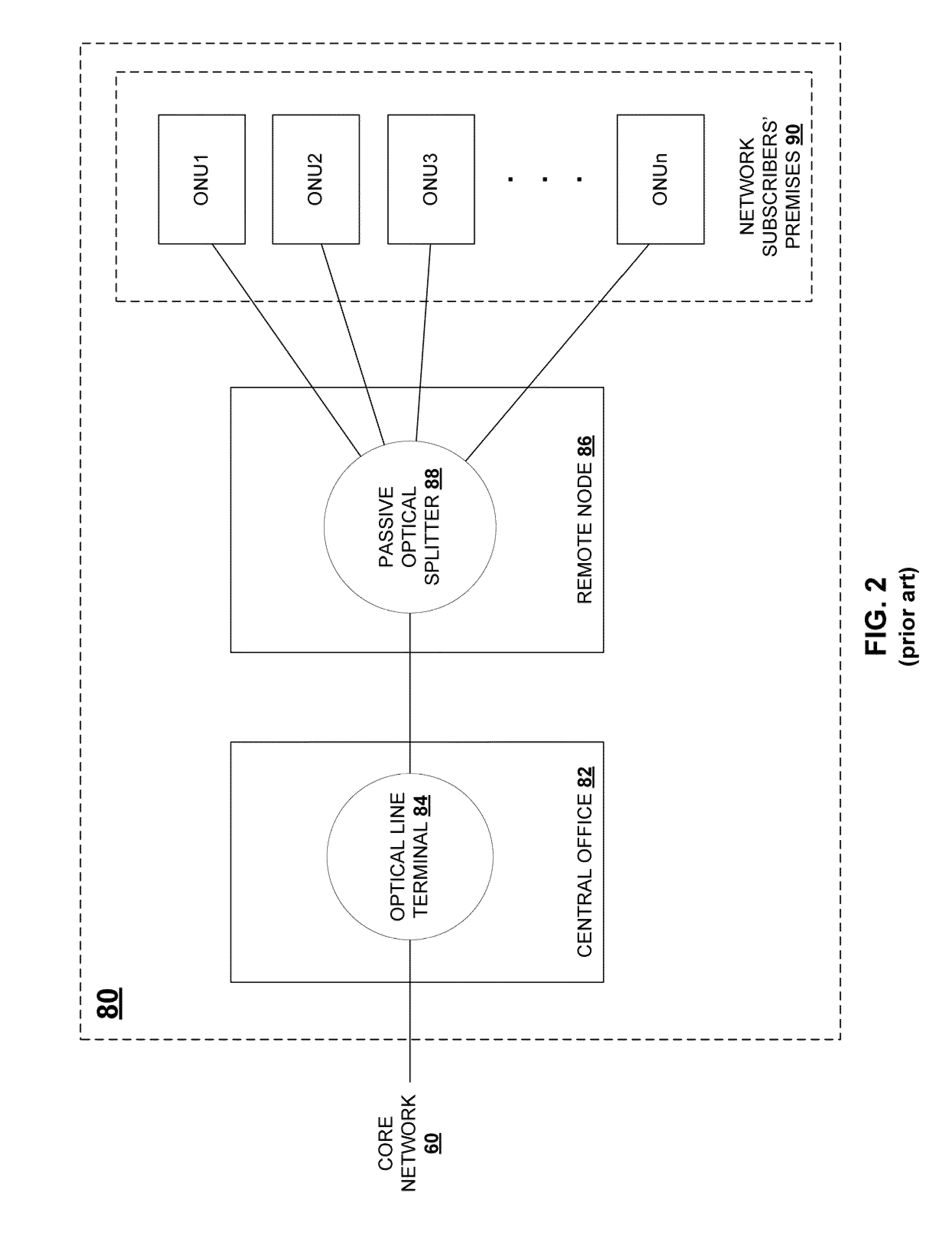
[0025]Aspects of the invention are directed to structures and techniques for use in MCF transmission applications in the areas of (1) high performance super-computers and data centers, (2) core networks, and (3) optical access networks.

[0026]There are significant differences in the system requirements and transceiver technologies for applications in these three contexts. Hence, the structures and techniques used to provide connectivity between individual transceivers and MCF will be different.

[0027]The present description is organized as follows:[0028]1. Data Centers[0029]2. Core Networks[0030]3. Optical Access Networks[0031]4. Summary[0032]5. Conclusion

1. HIGH-PERFORMANCE SUPER-COMPUTERS AND DATA CENTERS

[0033]Data centers and high-performance computing environments typically include thousands, or tens of thousands, of optical links. The longest of these optical links typically has a length of less than 100 m. The key requirements for ensuring successful deployment of these high-spe...


PUM


Abstract

An optical data link includes first and second pluralities of transmission devices, at least one of which is configured as an array. A multichannel transmission link has a first end connected to the first plurality of transmission devices and a second end connected to the second plurality of transmission devices so as to form a plurality of parallel transmission channels therebetween. The multichannel transmission link includes a multicore fiber with a plurality of individual cores having a configuration matching the array configuration of the at least one plurality of transmission devices. The multicore fiber has an endface connected directly to the at least one plurality of transmission devices, with the individual cores of the multicore fiber aligned with respective devices in the at least one plurality of transmission devices. Further described are access networks and core networks incorporating a transmission link comprising at least one span of a multicore fiber.

Description

CROSS REFERENCE TO RELATED APPLICATIONS[0001]The present application claims the priority benefit of the following United States provisional patent application, which is owned by the assignee of the present application, and which is incorporated herein by reference in its entirety:[0002]U.S. Prov. Pat. App. Ser. No. 61 / 314,183, filed on Mar. 16, 2010; and[0003]U.S. Prov. Pat. App. Ser. No. 61 / 312,497, filed on Mar. 10, 2010.BACKGROUND OF THE INVENTION[0004]1. Field of the Invention[0005]The present invention relates generally to multicore fiber transmission systems and methods.[0006]2. Background Art[0007]Rapid and global increasing of internet services has been accelerating the needs for large-capacity optical fiber communications. FIG. 1 shows a simplified diagram of an exemplary optical network architecture 20 according to the prior art. The network architecture includes a data center 40 that transmits and receives data over a core network 60. An access network 80 is connected int...

Claims


Application Information

Patent Timeline
Patent Type & Authority Applications(United States)
IPC IPC(8): H04B10/12H04B10/00H04B10/2581
CPCG02B6/02042G02B6/4249H04J14/00H04J14/04H04J14/0282H04J14/0246H04J14/025H04J14/02
Inventor FINI, JOHN M.TAUNAY, THIERRY F.YAN, MAN F.ZHU, BENYUAN
Owner OFS FITEL LLC
Why Eureka
Try Eureka