Electric de-icing device and related monitoring system

a technology of electric de-icing and monitoring system, which is applied in the direction of electric digital data processing, jet propulsion plants, instruments, etc., can solve the problems of affecting the aerodynamic properties of the air intake, affecting the safety of the flight, and disrupting the air conveyance towards the fan, so as to reduce the power and avoid overheating the lip

Active Publication Date: 2011-11-17
SAFRAN NACELLES
View PDF11 Cites 20 Cited by
  • Summary
  • Abstract
  • Description
  • Claims
  • Application Information

AI Technical Summary

Benefits of technology

This deteriorated mode corresponds to the sending of a warning message to the pilot to warn him to leave the icing conditions as soon as possible. And depending on the scenario, it is possible either to decrease the power to avoid overheating the lip, or to maintain the deicing power to protect the engine from ice.

Problems solved by technology

The presence of ice or frost alters the aerodynamic properties of the air intake and disrupts the conveyance of air towards the fan.
Furthermore, the formation of ice on the air intake of the nacelle and the ingestion of ice by the engine in the event blocks of ice detach can damage the engine, and present a safety risk for the flight.
However, such a device requires a system of hot air intake pipes between the turbojet engine and the air intake, as well as a system for evacuating hot air at the air intake lip.
This increases the mass of the propulsion assembly, which is not desirable.
The use of these materials poses certain problems in the context of an electrical deicing device.
Indeed, the exposure temperature of these materials generally must not exceed a critical threshold, subject to distorting the material and therefore damaging the structure.
However, such a solution does not make it possible to avoid certain local overheating between the sensors without substantially increasing the number of temperature sensors used.
Such a solution also involves establishing a data transfer network for the data measured by the sensor, which makes the structure heavier and can make the deicing device particularly complex and not very practical in terms of its installation and implementation.
For reliability reasons, it could also be necessary to make the sensors redundant, which would further affect the mass of the structure and increase the complexity thereof.
Moreover, combining the electrical power supply and measurement chains for a plurality of resistant mats creates a new problem, i.e. monitoring the integrity of the heating mats.

Method used


Image

  • Electric de-icing device and related monitoring system
  • Electric de-icing device and related monitoring system
  • Electric de-icing device and related monitoring system

Examples


Embodiment Construction

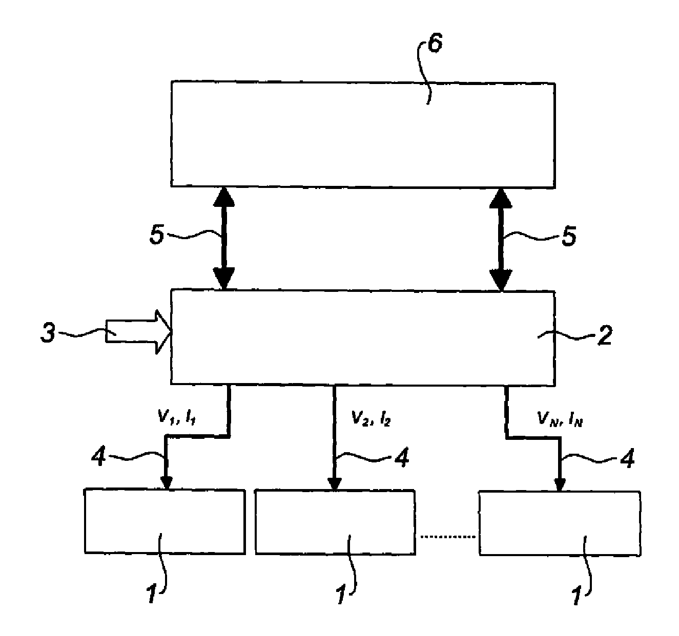
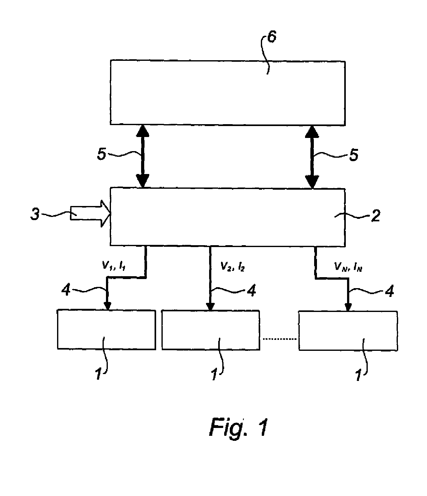
FIG. 1 diagrams a control device of an electric deicing system of an air intake of a turbojet engine nacelle as shown in FIG. 2.

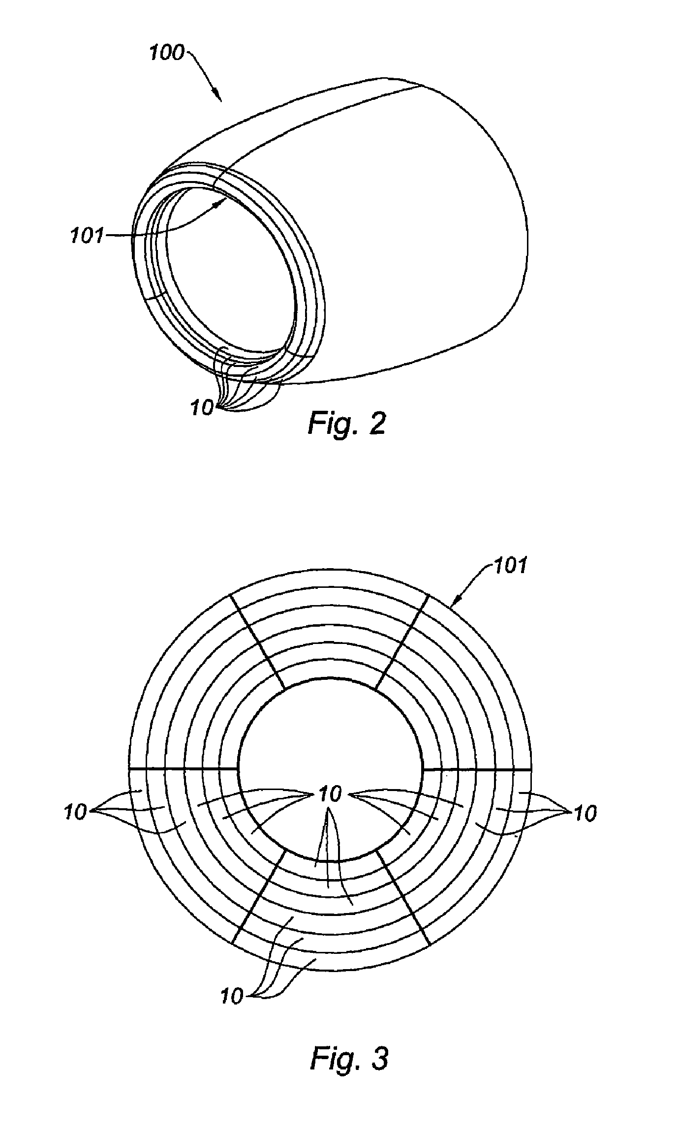
This air intake 100 is equipped with a plurality of heating resistances grouped together in heating resistant mats 10 grouped together in assemblies 1 of resistant mats 10.

Advantageously, each assembly 1 of resistant mats 10 corresponds to a specific zone of an air intake lip 101.

In the illustrated scenario, the air intake 101 is divided into six peripheral zones and six sectors and therefore includes thirty-six resistant mats 10.

The six resistant mats 10 of the peripheral zones form an assembly 1 of resistant mats over two sectors. There are therefore three assemblies 1 of twelve resistant mats 10.

The three assemblies 1 of resistant mats 12 respectively correspond to a zone situated near the inside (Int) of the air intake lip 101, a zone situated at the air intake lip 101, and a zone situated slightly upstream of the air intake lip 101.

In fact, these diffe...


PUM


Abstract

The invention relates to a de-icing device for an element of a nacelle of a turbojet engine, including at least one heating resistant mat connected to at least one electrical power source (3) and thus defining an assembly (1) of resistant mats, characterised in that the assembly of resistant mats includes one or more subassemblies of resistant mats, each subassembly in turn including one or more resistant mats of the assembly, and each subassembly of resistive mats having a different ohmic value.

Description

TECHNICAL FIELDThe present invention relates to a deicing method, in particular for an air intake lip assembly of a turbojet engine nacelle.BACKGROUNDAn airplane is propelled by one or more propulsion assemblies each comprising a turbojet engine housed in a tubular nacelle. Each propulsion assembly is attached to the airplane by a pylon generally located under a wing or at the fuselage.A nacelle generally has a structure comprising an air intake upstream of the engine, a central section intended to surround a fan of the turbojet engine, a downstream section housing thrust reverser means and intended to surround the combustion chamber of the turbojet engine, and generally ends with a jet nozzle whereof the outlet is located downstream of the turbojet engine.The air intake comprises, on one hand, an air intake lip suitable for allowing optimal collection towards the turbojet engine of the air needed to supply the fan and internal compressors of the turbojet engine, and on the other ha...

Claims


Application Information

Patent Timeline
Patent Type & Authority Applications(United States)
IPC IPC(8): F02G3/00G06F19/00
CPCB64D15/12B64D2033/0233B64D15/20H05B3/026H05B3/0014B64D15/00F02C7/047
Inventor PEREIRA, DAVIDLEMAINS, LAURENCE
Owner SAFRAN NACELLES
Why Eureka
Try Eureka