Detecting and maintaining linearity in a power amplifier system through comparing peak and RMS power levels

a power amplifier and linearity technology, applied in the field of radio frequency transmission technology, can solve the problem of no longer practicable use of an isolator, achieve the effect of restoring linearity, increasing the ratio of peak power to rms power, and restoring linearity in the power amplifier

Inactive Publication Date: 2005-10-13
PANASONIC CORP
View PDF5 Cites 151 Cited by
  • Summary
  • Abstract
  • Description
  • Claims
  • Application Information

AI Technical Summary

Benefits of technology

[0010] The present invention provides a solution to the deficiencies in the current art by providing a technique to detect degradations in the linearity of a power amplifier and adjust the power level of the input signal to the power amplifier if degradations in the linearity of the power amplifier are detected. More specifically, the present invention operates to detect the output signal from a power amplifier. The peak power of the output signal is then determined. In addition, the average power, or the root-mean-square (RMS) power of at least a portion of the output signal is determined. When the linearity of the power amplifier begins to degrade, there is an increase in the ratio of the peak power to the RMS power. Thus, by monitoring the peak power and the RMS power levels, the present invention operates to detect degradation in the linearity of the power amplifier. The present invention then operates to restore linearity in the power amplifier by adjusting the power level of the signal being input to the power amplifier. The present invention can also restore linearity by adjusting the bias of the power amplifier or the power supply voltage to the power amplifier. Thus, the present invention operates to detect linearity in the operation of a power amplifier and to maintain linearity in the operation of the power amplifier. An additional aspect of the present invention is that the efficiency of the power amplifier can be improved. By monitoring the linearity of the power amplifier, the bias of the power amplifier can be lowered to improve efficiency without compromising linearity.

Problems solved by technology

Because isolators are typically large, expensive and support only narrow bandwidths (which requires the use of multiple large and expensive isolators in multi-band phones) it is no longer practical to use an isolator.

Method used


Image

  • Detecting and maintaining linearity in a power amplifier system through comparing peak and RMS power levels
  • Detecting and maintaining linearity in a power amplifier system through comparing peak and RMS power levels
  • Detecting and maintaining linearity in a power amplifier system through comparing peak and RMS power levels

Examples


Embodiment Construction

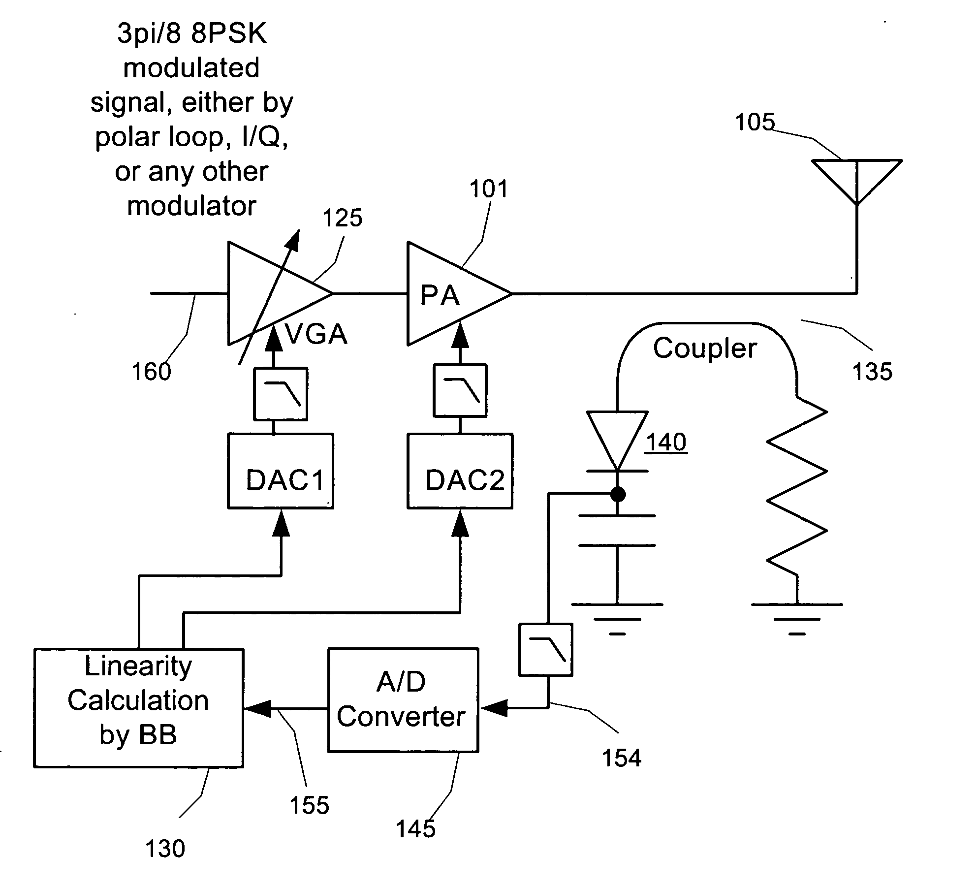
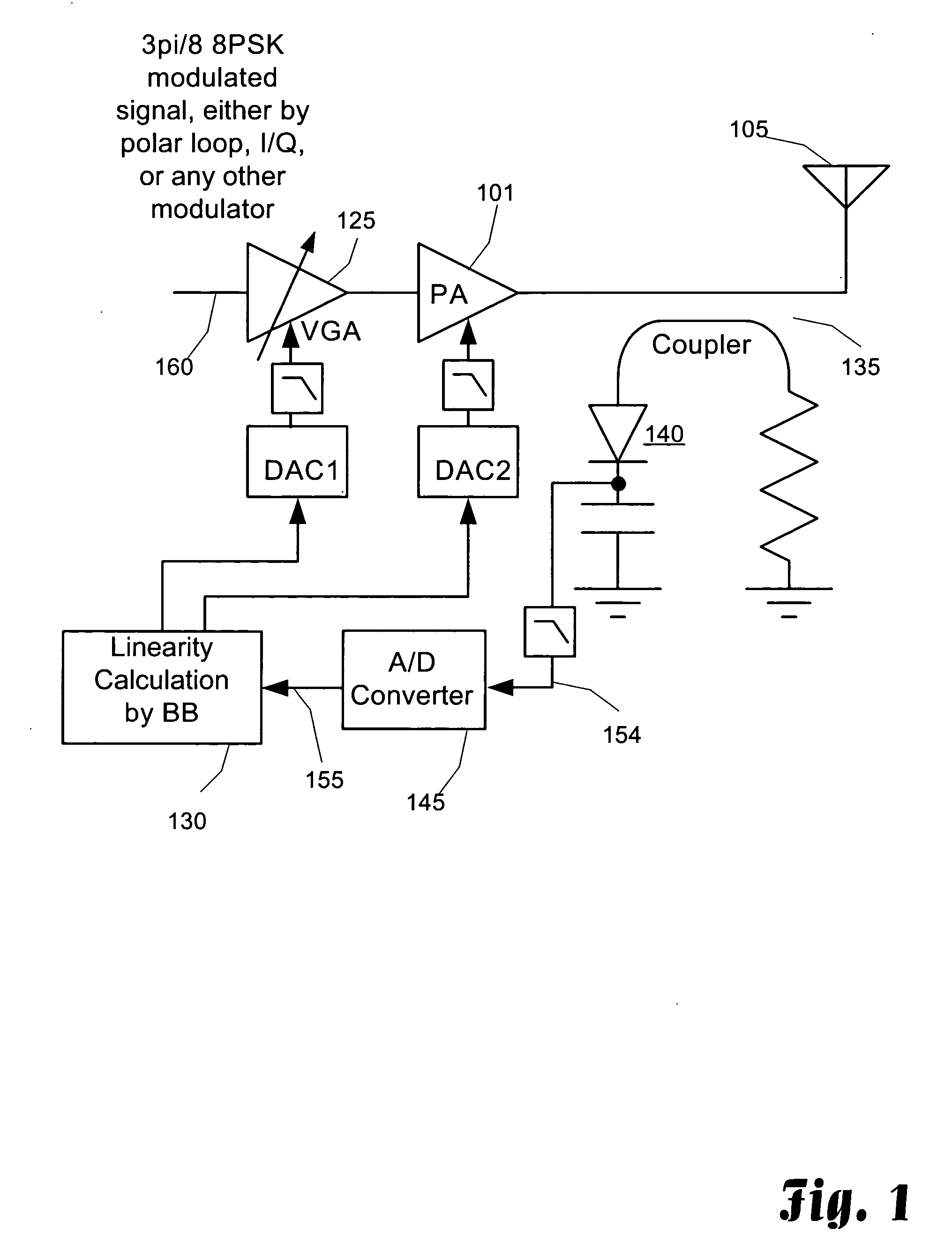
[0018] The present invention provides a solution to the above-describe problems and needs in the art. The present invention includes a method and circuit for detecting the linearity of a power amplifier system, and to maintain linearity within the power amplifier system. One benefit of the present invention is that the bias of the power amplifier can be lowered to improve efficiency while still monitoring and maintaining the linearity of the power amplifier. More specifically, several factors, such as the operating temperature, the level of the supply voltage and the load impedance, operate to destroy linearity in a power amplifier. EVM is used to measure the modulation quality of a 3π / 8 8PSK modulated signal and when the above-listed conditions are present, the amplitude error dominates the total EVM. AM to PM distortion affects the phase component of the 3π / 8 8PSK modulated signal at the power amplifier output, but has minimal affect to the overall EVM and can be ignored when tryi...


PUM


Abstract

Small portable communication devices that support multiple modulation techniques cannot gain the benefits of using an isolator at the output of a power amplifier to provide stability in the load impedance. However, for communication devices that include amplitude modulation schemes, maintaining linear operation of the power amplifier is still required. In the presence of unstable load impedance, this can be a difficult task. As a solution, the linearity of the power amplifier is detected by determining the peak power of the output signal and the average or root-mean-square of a portion of the output signal, such as a mid-amble). The ratio of the peak power and the average power of the output signal are used to determine if the power amplifier is operating in the linear region. If the ratio is too high, then the power amplifier may be operating in the linear region. By adjusting the power level of the input signal to the power amplifier when the ratio increases, linearity of the power amplifier is maintained.

Description

CROSS-REFERENCE TO RELATED APPLICATIONS [0001] This application is related to U.S. patent application Ser. No. __ / ______ entitled “DETECTING AND MAINTAINING LINEARITY IN A POWER AMPLIFIER SYSTEM THROUGH ENVELOPE POWER COMPARISONS” filed on the same date at this application and commonly assigned to the assignee of this application, which application is incorporated herein by reference in its entirety.TECHNICAL FIELD [0002] The present invention is directed towards radio frequency transmission technology and, more specifically, towards a technique to detect and maintain linearity in a power amplifier for transmission systems that require linearity but do not have a stable output impedance or are susceptible to other conditions that can result in non-linear transmission. BACKGROUND [0003] Cellular telephone technology has greatly advanced since its inception in the early 80's. Today, several cellular technologies are deployed throughout the world. One of the more prominent of the cellu...

Claims


Application Information

Patent Timeline
Patent Type & Authority Applications(United States)
IPC IPC(8): H03F3/45H03G3/00H03G3/30H04B1/04
CPCH03F3/45192H03F3/45735H03F2200/513H04B1/0475H03G3/004H03G3/3042H03F2203/45424
Inventor YAMAZAKI, RYONOELLERT, WILLIAMPRATT, STEPHEN
Owner PANASONIC CORP
Why Eureka
Try Eureka