Tank fullness monitoring system

a fullness monitoring and tank technology, applied in the field of electronic sensing devices, can solve the problems of maintenance, mounting, calibration problems, cumbersome direct physical measurement, etc., and achieve the effect of improving the accuracy of the measurement, avoiding the occurrence of occlusion, and avoiding occlusion

Inactive Publication Date: 2011-11-17
GEOFORCE
View PDF39 Cites 20 Cited by
  • Summary
  • Abstract
  • Description
  • Claims
  • Application Information

AI Technical Summary

Problems solved by technology

However, measuring a fullness of a fluid storage tank can be difficult.
Direct physical measurement, such as via measurement rods or visual inspection, is cumbersome and can be inaccurate or slow.
Rigid float-based systems also can measure fluid levels, but deployment into a fluid storage tank present maintenance, mounting, and calibration problems.

Method used


Image

  • Tank fullness monitoring system
  • Tank fullness monitoring system
  • Tank fullness monitoring system

Examples


Embodiment Construction

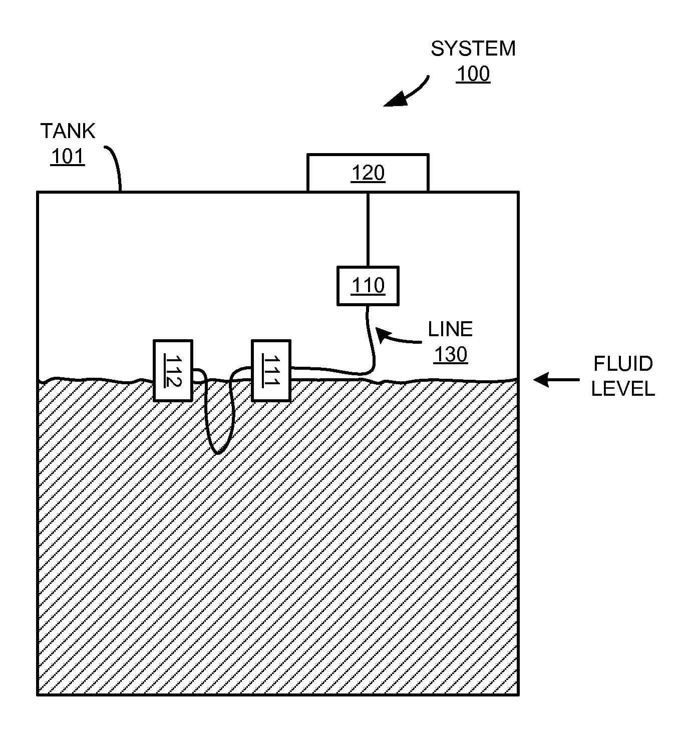
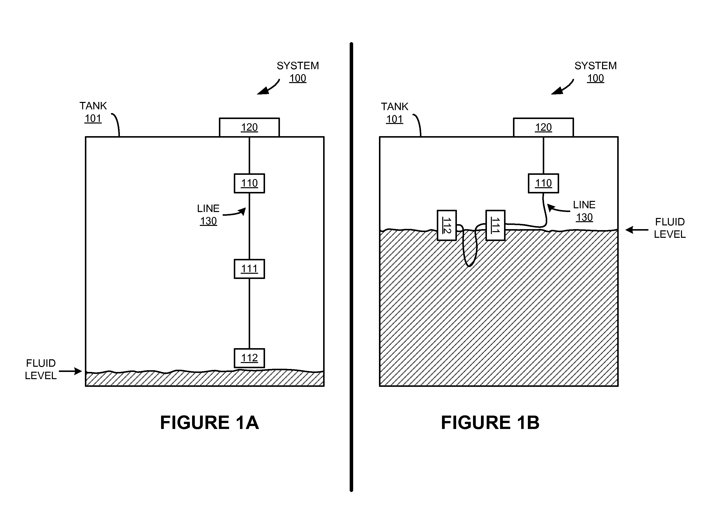
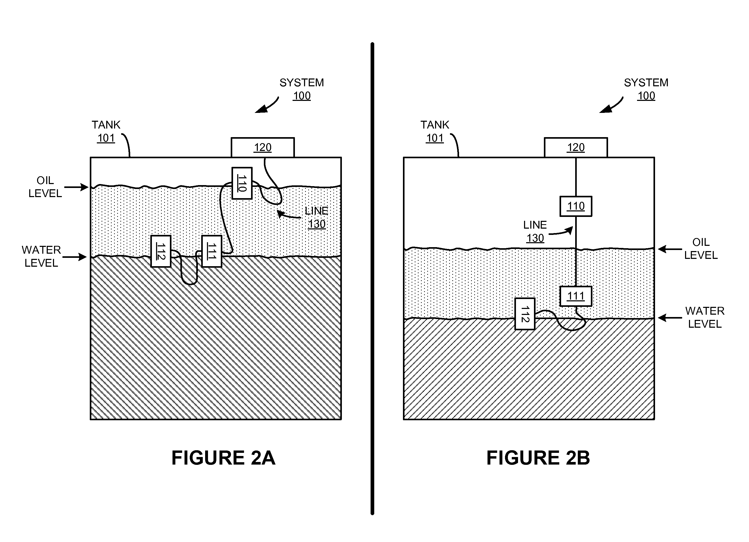
[0012]FIGS. 1A-1B and FIGS. 2A-2B are system diagrams illustrating tank fullness monitoring system 100. System 100 includes tank 101, control node 120, buoyant sensor nodes 110-112, and line 130. Control node 120 is attached to tank 101. Control node 120 and each of sensor nodes 110-112 communicate over line 130. Sensor nodes 110-112 also are coupled in series along line 130, with sensor node 110 coupled to control node 120. Tank 101 comprises a vessel or container for fluids. Tank 101 could contain liquid, gas, or particulate contents.

[0013]Each of sensor nodes 110-112 is coupled to sensor node 120 in a series fashion along line 130. In this example, each of sensor nodes 110-112 is coupled electrically to control node 120 by line 130. Each of sensor nodes 110-112 includes a sensor portion and a buoyancy system. The sensor portion could comprise a mercury switch, magnetic switch, thermometers, thermocouples, thermopiles, emitters / detectors, microphones, accelerometers, strain gauges...


PUM


Abstract

What is disclosed is a tank fullness monitoring system. The tank fullness monitoring system includes a plurality of buoyant sensor nodes coupled in series along a line, where the buoyant sensor nodes are configured to hang in series along the line, and where each of the buoyant sensor nodes is configured to indicate when floating at a fluid interface. The tank fullness monitoring system also includes a control node attached to the tank and coupled to a first one of the buoyant sensor nodes, and configured to monitor the buoyant sensor nodes.

Description

RELATED APPLICATIONS[0001]This patent application is related to and claims priority to U.S. Provisional Patent Application No. 61 / 333,464, entitled “Tank Fullness Monitoring System,” filed on May 11, 2010, which is hereby incorporated by reference in its entirety.TECHNICAL FIELD[0002]Aspects of the disclosure are related to the field of electronic sensing devices, and in particular, tank fullness sensing devices.TECHNICAL BACKGROUND[0003]Fluid storage tanks are used in a variety of liquid and gas storage systems, such as for storing water, oil, gasoline, chemicals, or other substances. However, measuring a fullness of a fluid storage tank can be difficult. Direct physical measurement, such as via measurement rods or visual inspection, is cumbersome and can be inaccurate or slow. Rigid float-based systems also can measure fluid levels, but deployment into a fluid storage tank present maintenance, mounting, and calibration problems.Overview[0004]What is disclosed is a tank fullness mo...

Claims


Application Information

Patent Timeline
Patent Type & Authority Applications(United States)
IPC IPC(8): G01F23/44
CPCG01F23/44G01F23/0038G01F23/76G01F23/68
Inventor ARMITAGE, DAVID L.KUSHNIR, GREGORY FROIMMASON, MARK ALVIN
Owner GEOFORCE
Why Eureka
Try Eureka