High spatial resolution fiber optic temperature sensor

a fiber optic and temperature sensor technology, applied in the field of temperature sensing, can solve the problems of inability to provide an accurate measurement, limited avenue, reliability issues,

Active Publication Date: 2014-01-14
SENSORTRAN
View PDF28 Cites 22 Cited by
  • Summary
  • Abstract
  • Description
  • Claims
  • Application Information

AI Technical Summary

Problems solved by technology

Each of these sensors has a resolution of about 1 meter, which may not provide an accurate measurement.
Further, the use of the multiple sensors to compensate for the inaccurate measurement is expensive to manufacture and is physically and electrically complex, thus causing rise to reliability issues.
But that avenue is limited in the quest for major improvements in spatial resolution.

Method used


Image

  • High spatial resolution fiber optic temperature sensor
  • High spatial resolution fiber optic temperature sensor
  • High spatial resolution fiber optic temperature sensor

Examples


Embodiment Construction

[0025]Preferred embodiments and their advantages are best understood by reference to FIGS. 1 through 11, wherein like numbers are used to indicate like and corresponding parts.

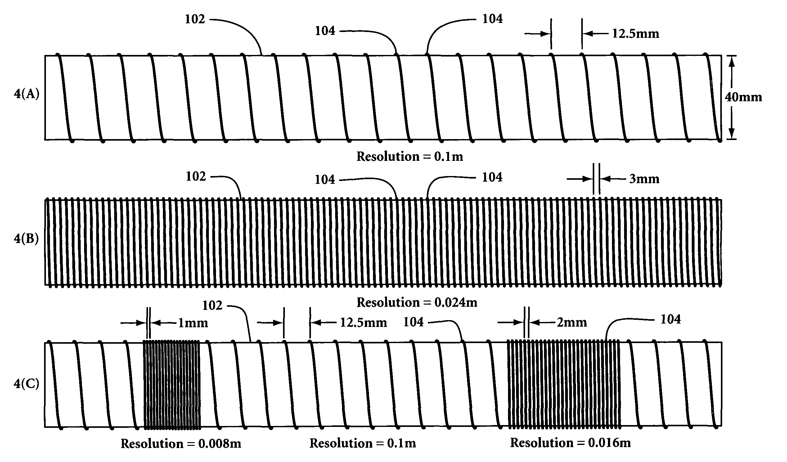
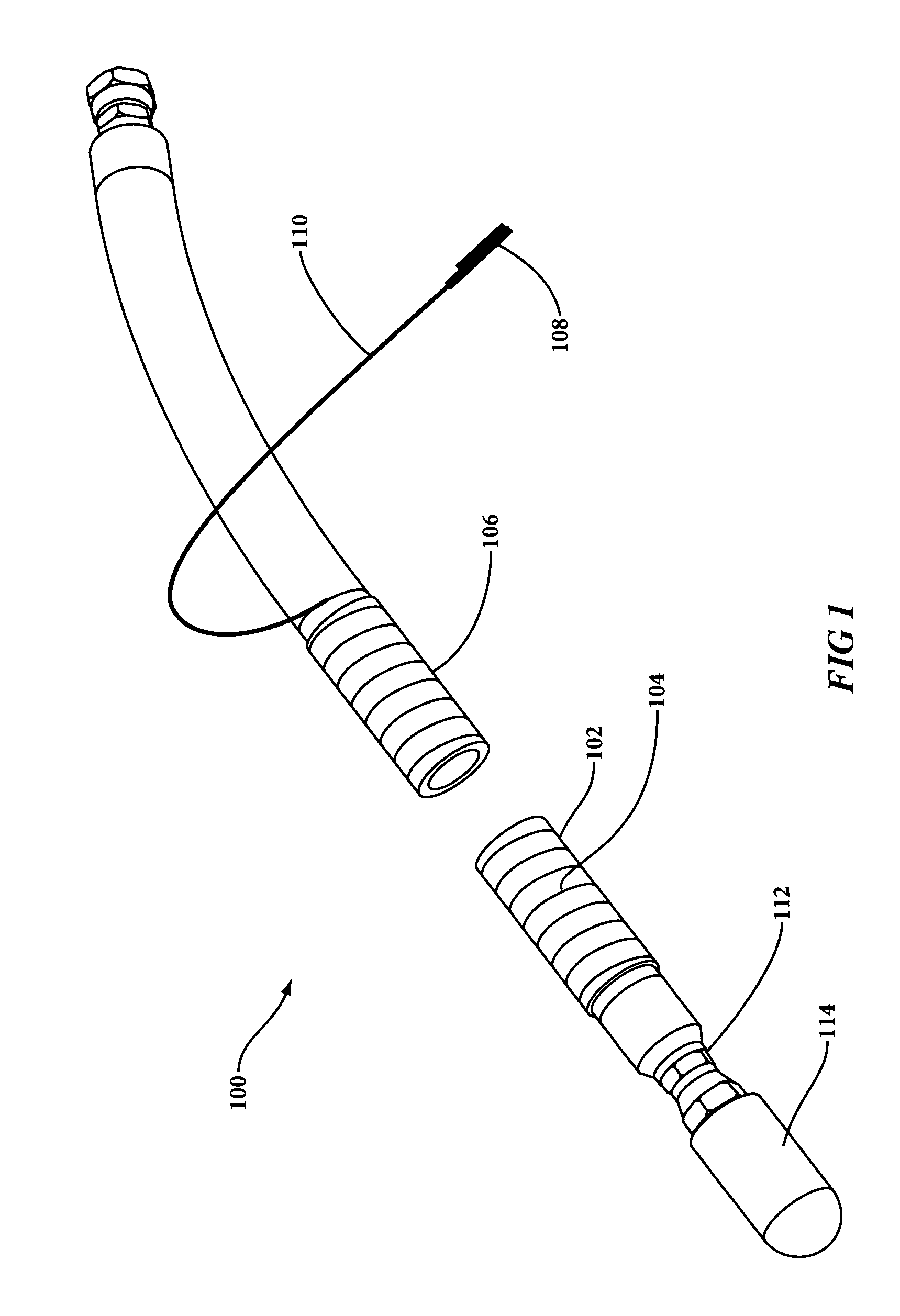
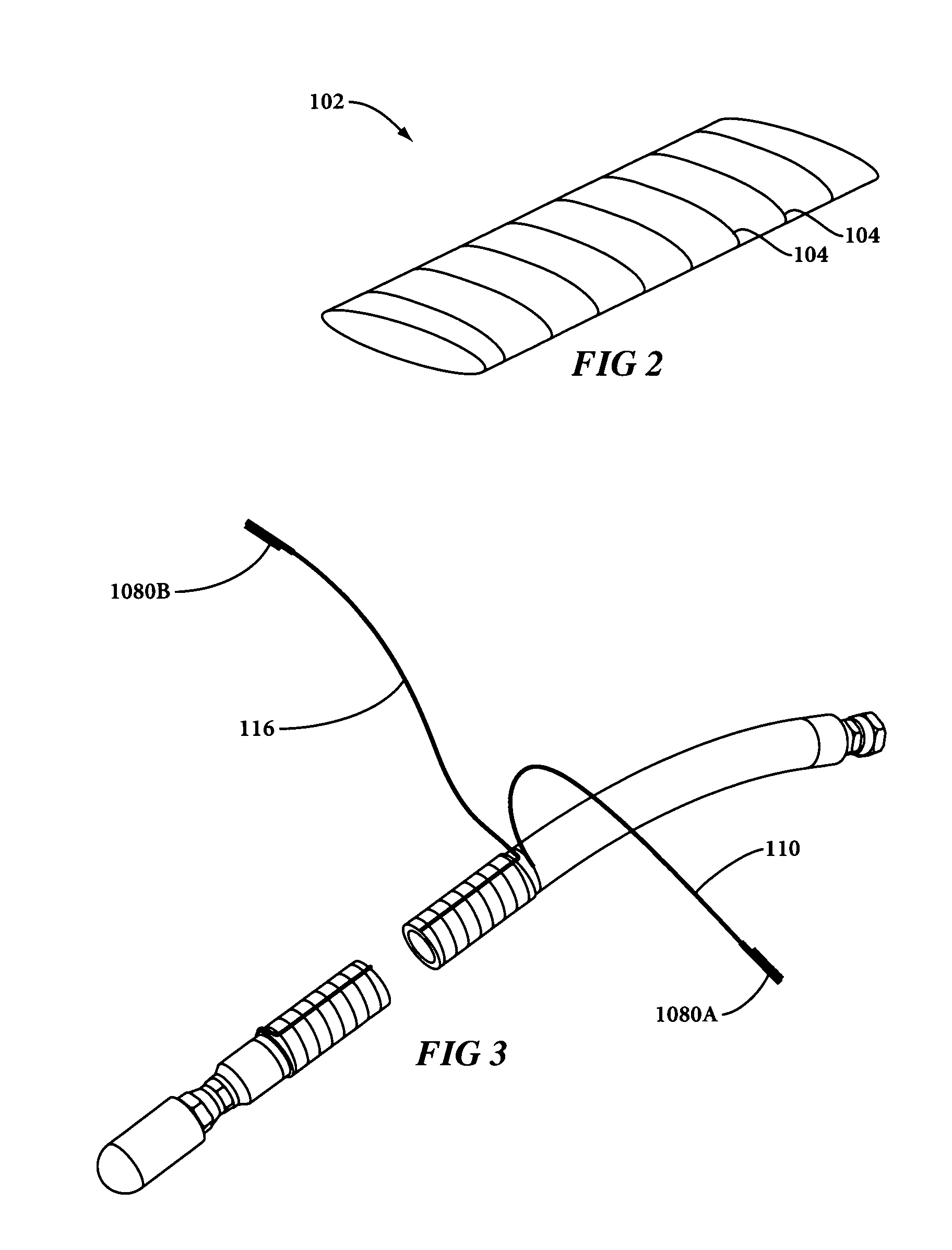
[0026]The present disclosure provides systems and methods for increasing the spatial resolution of a distributed temperature sensing system by creating new sensors especially adapted to improve spatial resolution by significantly increasing the density of fiber at desired locations by wrapping an optical fiber along a sensor carrier at a specific pitch. The term pitch in this context is used as a metric for how closely wrapped the fiber is around the carrier and is explained later in the discussion of FIG. 4. The sensor carrier may be, for example, a flexible or non-flexible cylinder or other geometric shape (e.g., a cylinder, a cone, a sphere, a hemisphere, a toroid, a cube, a prism, a pyramid, a rectangle, etc.) that may be used to determine parameters such as, for example, temperature, depth of fluids, and ...


PUM

PropertyMeasurementUnit
diameteraaaaaaaaaa
diameteraaaaaaaaaa
diameteraaaaaaaaaa

Abstract

High resolution distributed temperature sensors using fiber optic distributed temperature sensing systems deployed on various carriers to significantly improve spatial resolution and provide high resolution temperature profile and detection of fluid or fluid interface levels.

Description

[0001]This application claims the priority of U.S. provisional 61 / 199,480 (Nov. 17, 2008).BACKGROUND OF THE INVENTION[0002]The present invention relates generally to temperature sensing and, more particularly, to improving spatial resolution in a distributed temperature sensing system by the use of special sensor configurations.[0003]Fiber optic Distributed Temperature Sensing (DTS) systems developed in the 1980s to replace thermocouple and thermistor based temperature measurement systems. DTS technology is based on Optical Time-Domain Reflectometry (OTDR) and utilizes techniques originally derived from telecommunications cable testing. Today DTS provides a cost-effective way of obtaining hundreds, or even thousands, of highly accurate, high-resolution temperature measurements, DTS systems today find widespread acceptance in industries such as oil and gas, electrical power, and process control.[0004]The underlying principle involved in DTS-based measurements is the detection of spon...

Claims


Application Information

Patent Timeline
Patent Type & Authority Patents(United States)
IPC IPC(8): G01J5/08H04J14/02G01K13/02G01K11/30G01K11/12G01J5/00G01J3/42G01F23/00
CPCG01F23/22G01F23/292G01K11/32
Inventor PARK, BRIANFASSIH-NIA, MOHAMMEDMCCOY, BRIAN K.KALAR, KENTJAASKELAINEN, KARI-MIKKO
Owner SENSORTRAN
Why Eureka
Try Eureka