Single wafer dryer and drying methods

a technology of wafer dryer and substrate, which is applied in the direction of cleaning with liquids, lighting and heating apparatus, furnaces, etc., can solve the problems of subsequent device failure, spotting, and residue left on the surface of the substrate, and achieve the effect of reducing the ra

Inactive Publication Date: 2009-04-07
APPLIED MATERIALS INC
View PDF131 Cites 21 Cited by
  • Summary
  • Abstract
  • Description
  • Claims
  • Application Information

AI Technical Summary

Problems solved by technology

After removal from the rinsing bath, absent use of a drying apparatus, the bath fluid would evaporate from the substrate's surface causing streaking, spotting and / or leaving bath residue on the surface of the substrate.
Such streaking, spotting and residue can cause subsequent device failure.

Method used


Image

  • Single wafer dryer and drying methods
  • Single wafer dryer and drying methods
  • Single wafer dryer and drying methods

Examples


Embodiment Construction

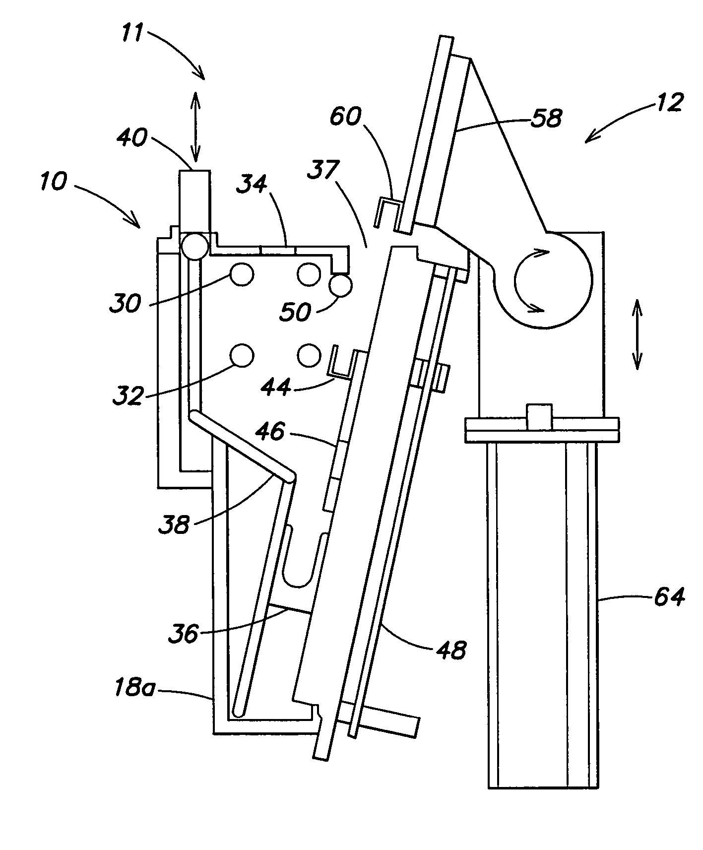
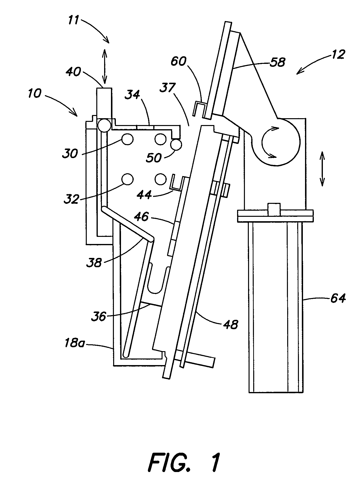
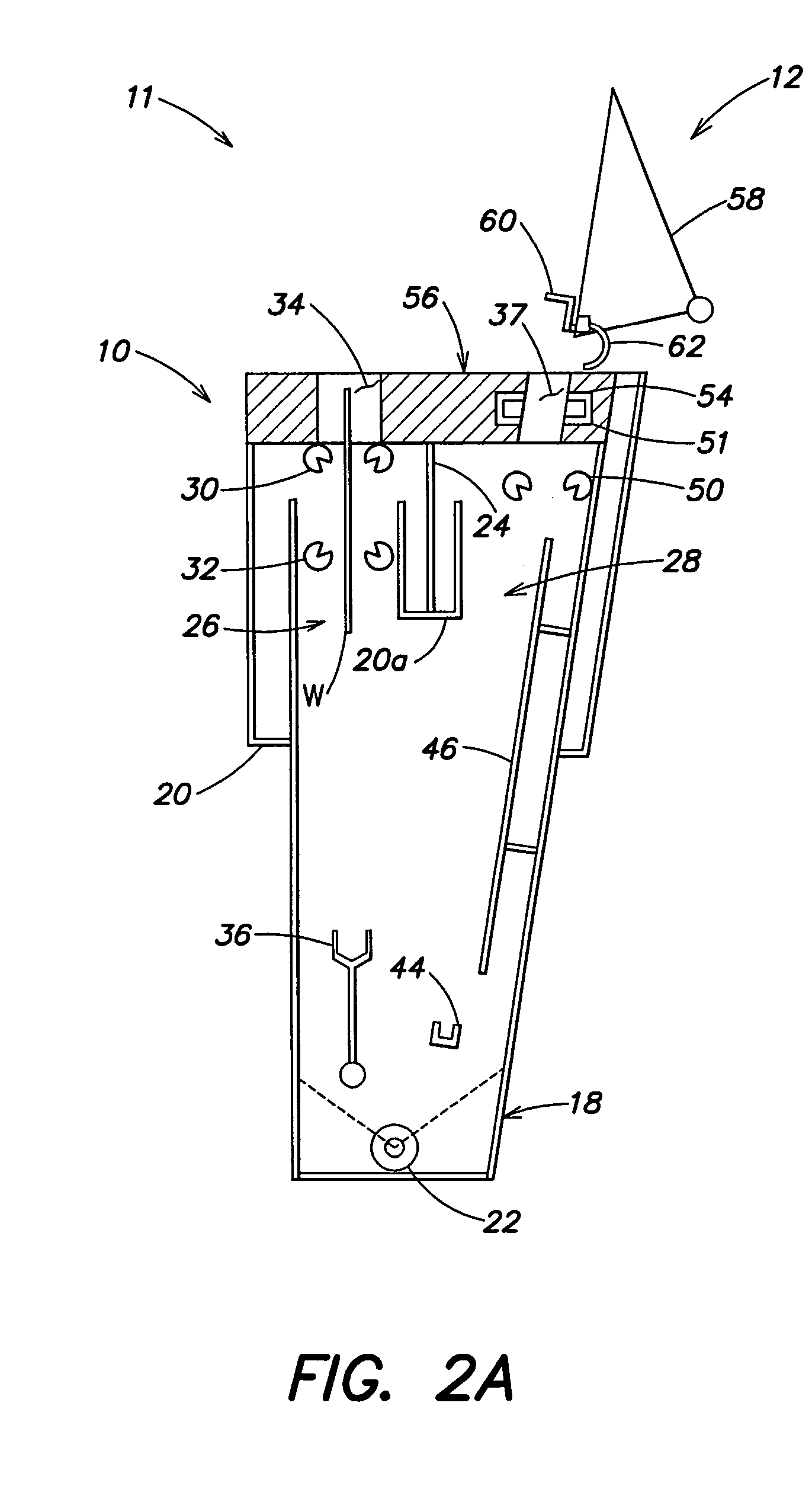
[0019]A drying apparatus provided in accordance with the present invention comprises a processing portion and an output portion. The processing portion includes a main chamber that may be configured according to two main aspects. A first aspect (submersion chamber 18a) submerges a wafer in a bath of fluid and is shown and described with reference to FIGS. 1-2I; a second aspect (spray chamber 18b) sprays an unsubmerged wafer with fluid and is shown and described with reference to FIG. 5.

[0020]Similarly, the output portion includes an output platform that may be configured according to two main aspects. A first aspect (rotation platform 58) rotates a wafer from a generally vertical orientation to a generally horizontal orientation and is shown and described with reference to FIGS. 1-2I; a second aspect (translation platform 158) translates horizontally so as to receive a generally vertically oriented wafer in one of a plurality of wafer receivers, and is shown and described with refer...


PUM


Abstract

In a first aspect, a first method of drying a substrate is provided. The first method includes the steps of (1) lifting a substrate through an air / fluid interface at a first rate; (2) directing a drying vapor at the air / fluid interface during lifting of the substrate; and (3) while a portion of the substrate remains in the air / fluid interface, reducing a rate at which a remainder of the substrate is lifted through the air / fluid interface to a second rate. The drying vapor may form an angle of about 23° with the air / fluid interface and / or the second rate may be about 2.5 mm / sec.

Description

[0001]The present application is a continuation-in-part of and claims priority from U.S. patent application Ser. No. 10 / 286,404, filed Nov. 1, 2002, now U.S. Pat. No. 6,955,516 which claims priority from U.S. Provisional Patent Application Ser. No. 60 / 335,335, filed Nov. 2, 2001. The present application also claims priority from U.S. Provisional Patent Application Ser. No. 60 / 542,960, filed Feb. 9, 2004. All of the above patent applications are hereby incorporated by reference herein in their entirety.FIELD OF THE INVENTION[0002]This invention is concerned with semiconductor manufacturing and is more particularly concerned with techniques for drying a substrate.BACKGROUND OF THE INVENTION[0003]As semiconductor device geometries continue to decrease, the importance of ultra clean processing increases. Aqueous cleaning within a tank of fluid (or a bath) followed by a rinsing bath (e.g., within a separate tank, or by replacing the cleaning tank fluid) achieves desirable cleaning levels...

Claims


Application Information

Patent Timeline
Patent Type & Authority Patents(United States)
IPC IPC(8): F26B3/00B08B3/00B05D3/02H01L21/00H01L21/306
CPCH01L21/02052H01L21/67034
Inventor ACHKIRE, YOUNESLERNER, ALEXANDER NGOVZMAN, BORISFISHKIN, BORISSUGARMAN, MICHAEL NMAVLIEV, RASHID AFANG, HAOQUANLI, SHIJIANSHIRAZI, GUY ETANG, JIANSHE
Owner APPLIED MATERIALS INC
Why Eureka
Try Eureka