Parent Steerable Tricycle with Internal Steering Limiter

a technology of steering limiter and tricycle, which is applied in the direction of steering device, friction roller based transmission, cycle equipment, etc., can solve the problems of virtually impossible for a child riding the tricycle, or the adult, to get his fingers caught and pinched in the steering limiter mechanism, and achieves quick and easy disengagement of the child, substantial play between the key and the aperture

Active Publication Date: 2011-11-17
MGA ENTERTAINMENT
View PDF6 Cites 50 Cited by
  • Summary
  • Abstract
  • Description
  • Claims
  • Application Information

AI Technical Summary

Benefits of technology

The vehicle also has a child's steering disengaging mechanism whereby the child's handlebar or other steering handle may be selectively engaged and disengaged from the front wheel. When the child's handlebar is disengaged, the child's handlebar turns to the left or to the right independent of any turning of the front wheel. In this way, the parent can quickly and easily disengage the child's handlebar which allows the parent to do the actual steering from behind, while the child plays at steering without actually affecting the steering. The parent therefore does not have to fight the child's actions in order to steer the vehicle.
Because the mechanism that couples rotation of the parent steering column to rotation of the fork tube and that also acts as a steering limiter is located entirely within the hollow tricycle frame, it is virtually impossible for a child or an adult accompanying the child to get his or her fingers or other body parts pinched between parts of the mechanism. The mechanism is therefore very safe for use in a child's tricycle or other vehicle.

Problems solved by technology

Still further, the steering limiter and the parent steering linkage are constructed so that they reside within the hollow frame of the tricycle making it virtually impossible for a child riding the tricycle, or the adult who is accompanying the child rider, to get his fingers caught and pinched in the steering limiter mechanism.

Method used


Image

  • Parent Steerable Tricycle with Internal Steering Limiter
  • Parent Steerable Tricycle with Internal Steering Limiter
  • Parent Steerable Tricycle with Internal Steering Limiter

Examples


Embodiment Construction

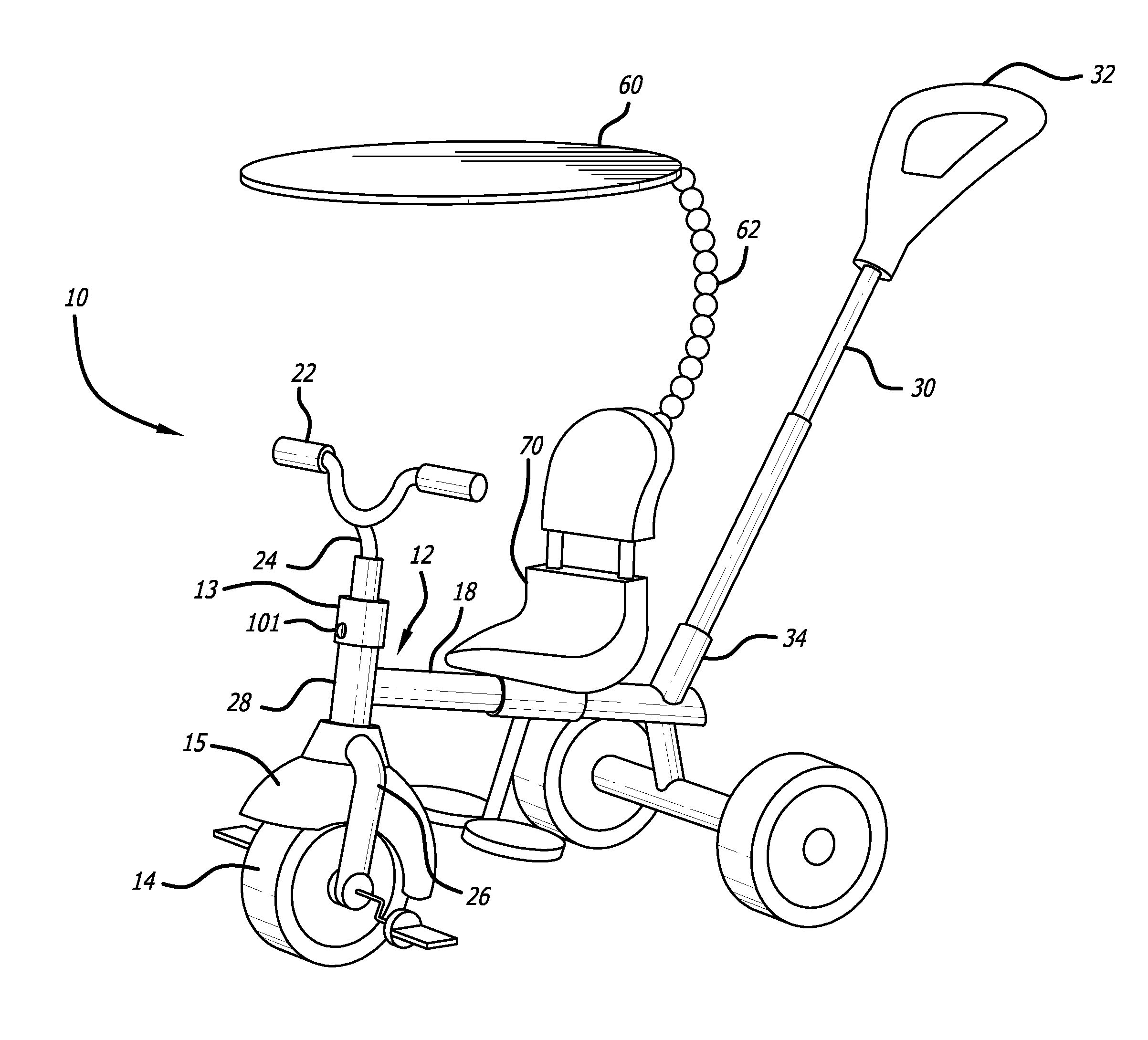
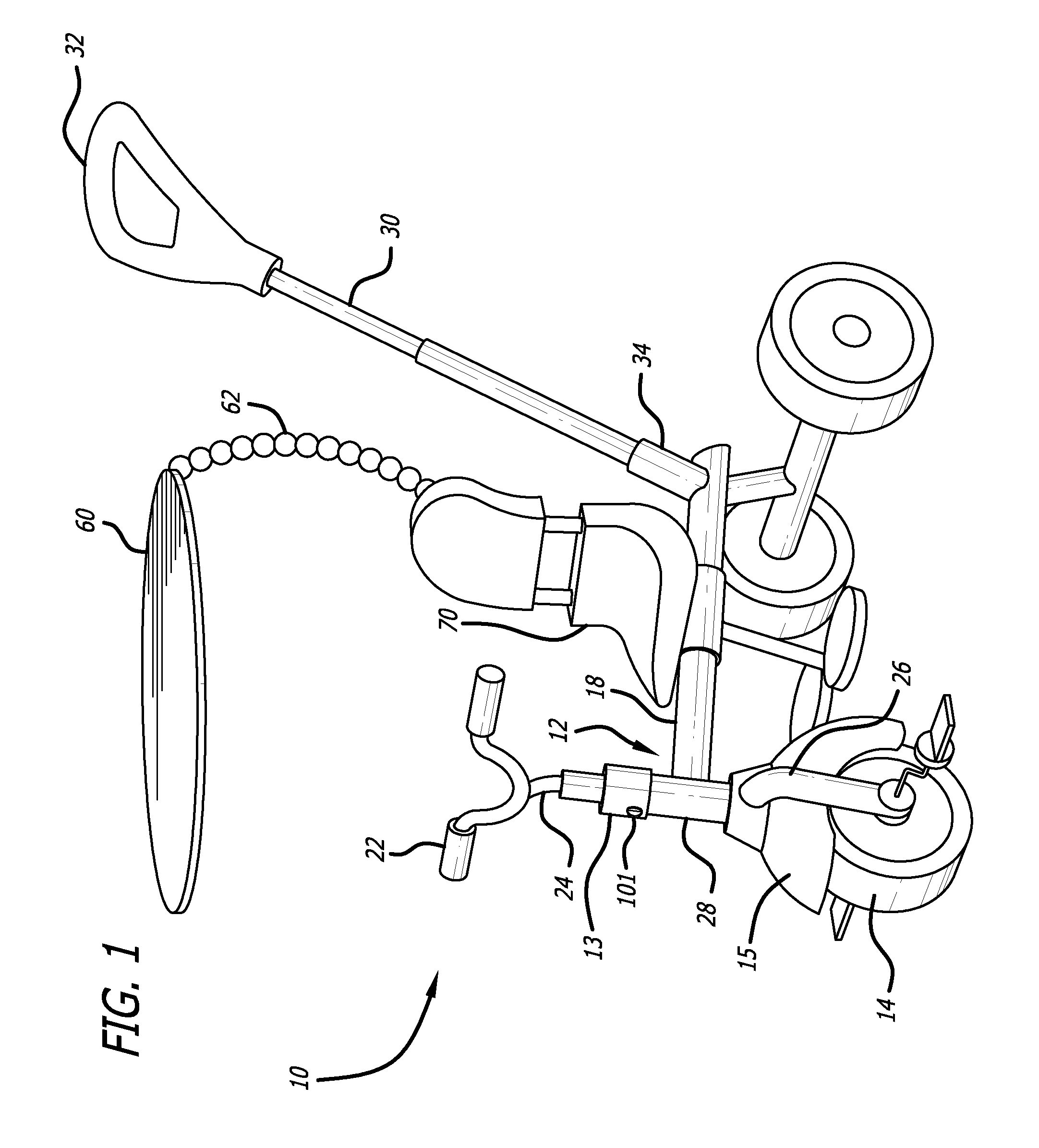
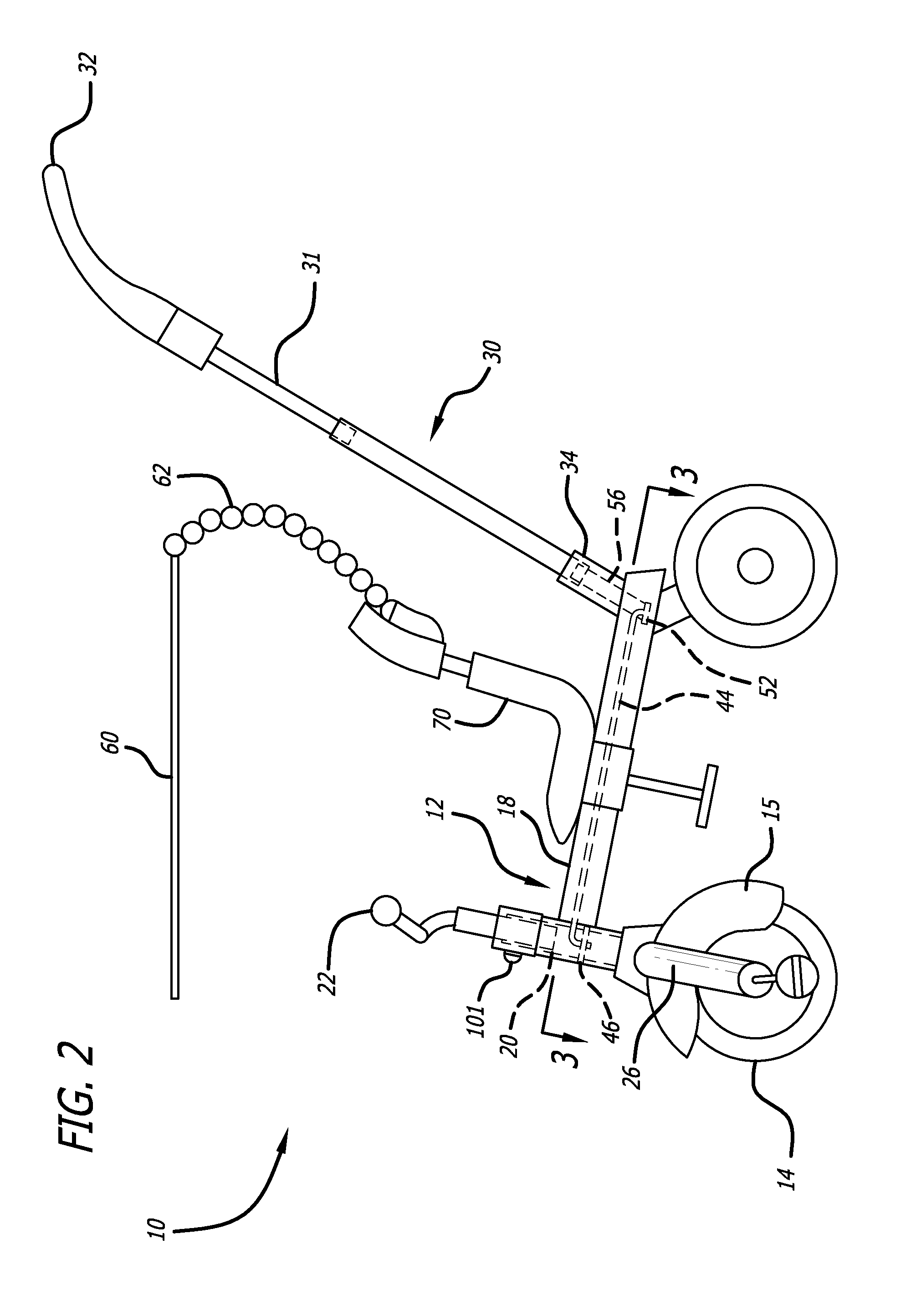
FIG. 1 is a side perspective view of the invention according to a first illustrative embodiment of a parent steerable tricycle with internal steering limiter according to the present invention. Although the vehicle in the embodiment is a tricycle, it will be understood that the invention can be applied to any child's vehicle. Tricycle 10 has a hollow frame 12 that includes a generally horizontally extending hollow cross tube 18 and a generally vertical hollow fork support tube 28 that are welded or otherwise affixed together. Steerable front wheel 14 and fender 15 are mounted to front wheel fork 26. Front wheel fork 26 includes fork tube 20 which is seen in FIG. 2 and FIG. 5. Fork tube 20 extends into fork support tube 28 and is rotatable within fork support tube 28 to provide steering to the front wheel. Rider platform 70 such as the seat shown is mounted to frame 12. Rider platform 70 need not be mounted directly to frame 12; rather the term “mounted to” contemplates both direct m...


PUM


Abstract

A child's riding vehicle such as a tricycle has a secondary steering column through which the parent walking behind the tricycle may steer the tricycle. The secondary steering column is coupled to the first steering column by a pair of rods that are attached at their respective ends to a first flange around the primary steering column and a second flange around the secondary steering column. The steering rods also act as steering limiters by contacting the wheel fork tube at a predetermined maximum steering angle and resisting further rotation of the flange. The mechanism lies entirely within the hollow frame of the tricycle for safety. The child's steering handle can be disengaged from the fork tube to allow the parent to completely control the steering without interference from the child.

Description

BACKGROUND OF THE INVENTION1. Field of the InventionThis invention relates to the field of riding vehicles. More particularly, this invention relates to the field of a riding vehicle such as a child's tricycle, having a separate steering mechanism by which the child's parent can steer the vehicle, and further having a steering limiting mechanism to prevent the front wheel(s) from being turned too far to the left or to the right, and further having a disengaging mechanism whereby the child's handlebar is disengaged from steering the front wheel.2. Description of Related ArtChildren's tricycles having provisions for locking the front wheel in a particular steering position are known. U.S. Pat. No. 6,082,754 issued to Jeunet et al. discloses a tricycle in which the front wheel can be locked in a forward-steering direction. Tricycles are also known that have not only a steering wheel lock, but also an additional handlebar so that a parent can push the tricycle and steer it like a stroll...

Claims


Application Information

Patent Timeline
Patent Type & Authority Applications(United States)
IPC IPC(8): B62K9/02B62K21/02
CPCB62J17/08B62K21/00B62K9/02B62H7/00
Inventor KHARE, SAMIRCASPI, YUVAL
Owner MGA ENTERTAINMENT
Why Eureka
Try Eureka