Recording apparatus

a technology of recording apparatus and inkjet, applied in printing and other directions, can solve problems such as degrading recording quality, and achieve the effect of simple positioning structur

Inactive Publication Date: 2011-11-17
CANON KK
View PDF4 Cites 11 Cited by
  • Summary
  • Abstract
  • Description
  • Claims
  • Application Information

AI Technical Summary

Benefits of technology

[0007]The present invention provides a recording apparatus capable of reliably cleaning a nozzle surface of a line-type recording head in which a plurality of nozzle chips is regularly arranged. The present invention also provides a recording apparatus cap

Problems solved by technology

Also, poor ink ejection resulting from clogging caused by intrusion of pape

Method used


Image

  • Recording apparatus
  • Recording apparatus
  • Recording apparatus

Examples


Embodiment Construction

ss="d_n">[0022]FIGS. 12A and 12B are side views that illustrate how the cleaning mechanism is operated.

[0023]FIG. 13 illustrates another example array of nozzle chips.

[0024]FIG. 14 is a flowchart of a cleaning operation sequence.

[0025]FIG. 15 illustrates a configuration of an example in which an absorber is employed as a suction portion.

[0026]FIGS. 16A and 16B are enlarged views of a reference member and its adjacent areas.

[0027]FIGS. 17A to 17C illustrate positional relationships between the reference member and a positioning member.

DESCRIPTION OF THE EMBODIMENTS

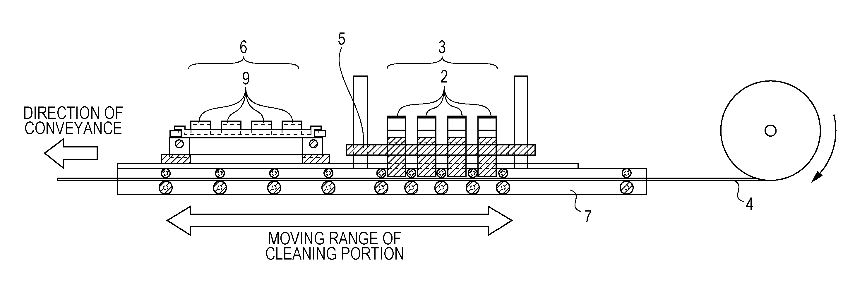
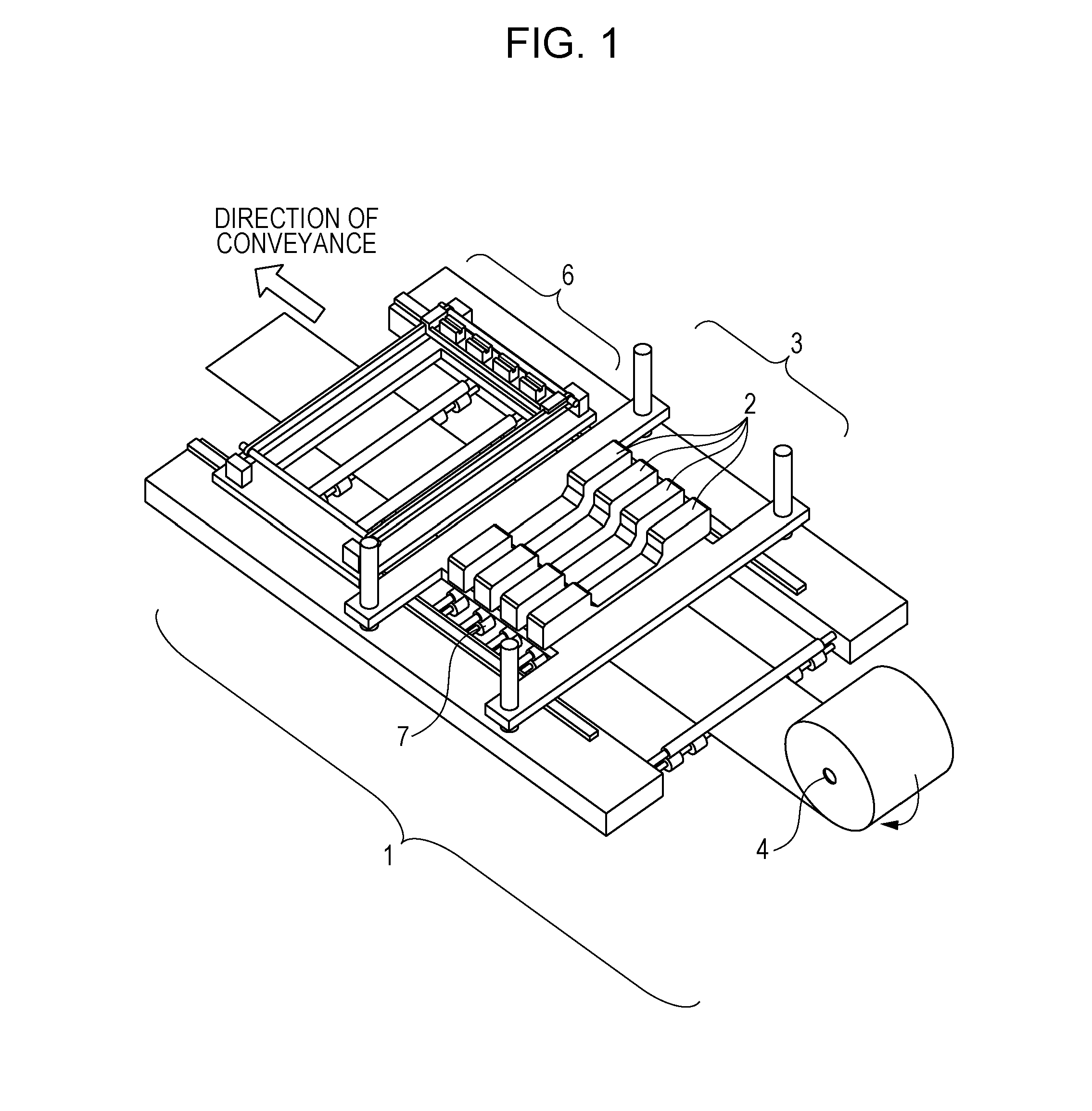
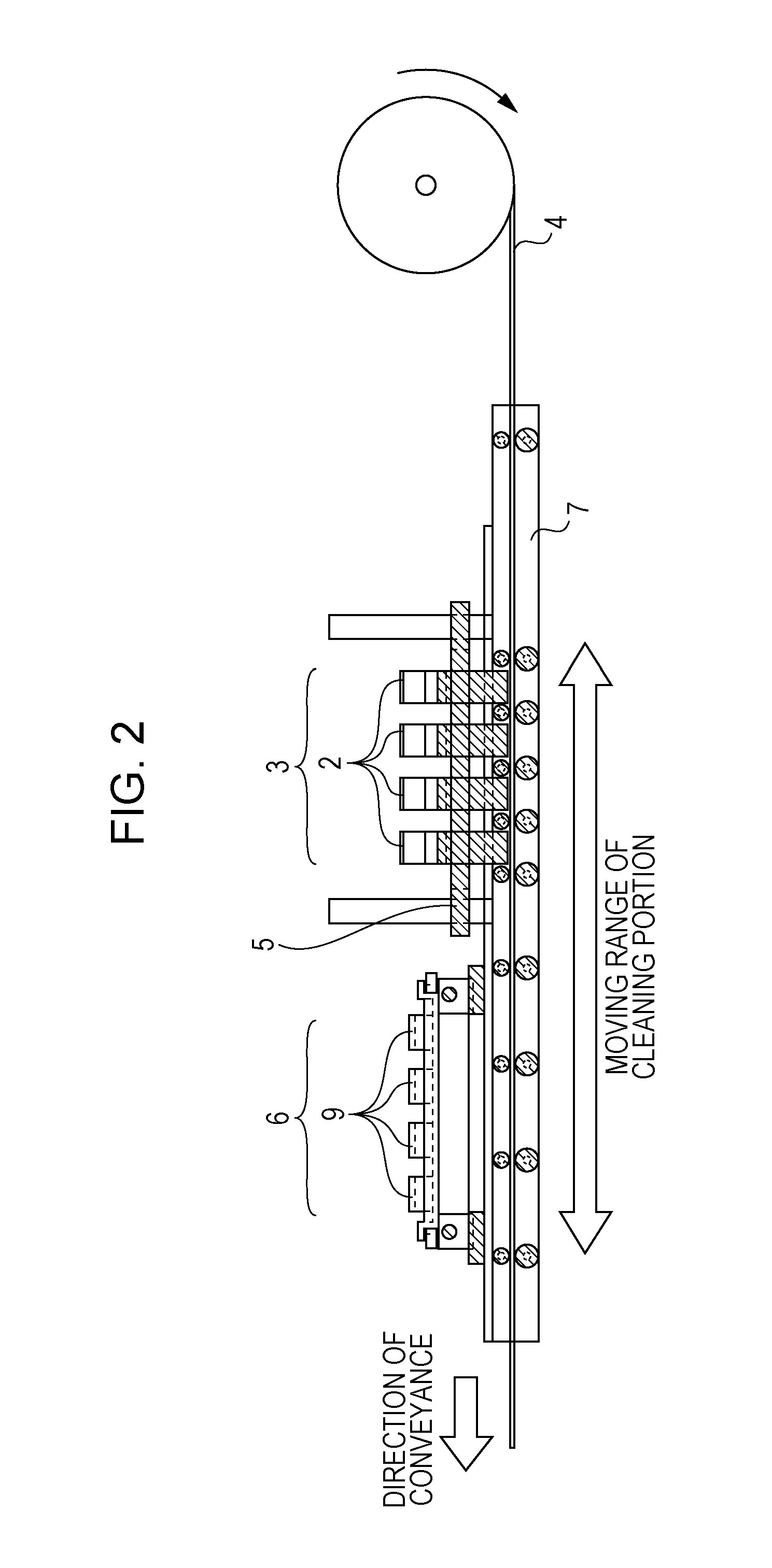
[0028]Embodiments of the present invention are specifically described with reference to the drawings. FIG. 1 is a perspective view that illustrates a configuration of a main section substantially centered on a recording portion of a recording apparatus according to an embodiment of the present invention. FIG. 2 illustrates a cross-sectional structure of the main section in FIG. 1. FIG. 3 is a cross-sectional view that illus...


PUM


Abstract

An apparatus includes a recording head having nozzle chips arranged in a staggered configuration along a second direction that intersects a first direction in which a sheet is conveyed, a first suction portion corresponding to a first row of nozzle chips in the staggered configuration, and a second suction portion corresponding to a second row of nozzle chips. The first suction portion and the second suction port are in a positional relationship in which they are displaced in the second direction so as to correspond to displacement between a first nozzle chip in the first row and its neighboring second nozzle chip in the second row in the second direction. The apparatus further includes a positioning member having a plurality of reference surfaces for use in positioning the recording head at different locations in a third direction that intersects the first direction and the second direction.

Description

BACKGROUND OF THE INVENTION[0001]1. Field of the Invention[0002]The present invention relates to an inkjet recording apparatus using a line-type recording head.[0003]2. Description of the Related Art[0004]For an inkjet recording apparatus, dry ink in a nozzle of a head may become thickened and stick to the nozzle. Also, poor ink ejection resulting from clogging caused by intrusion of paper lint, dust, or bubbles into ink in a nozzle may degrade recording quality. To address these conditions, the recording head needs cleaning.[0005]Japanese Patent Laid-Open No. 5-201028 discloses a cleaning mechanism that aims at recovery by forcibly sucking ink from a recording head. This cleaning mechanism includes a suction port shorter than the full length of a row of nozzles of the recording head and performs suction on all of the nozzles while moving the suction port along a direction in which the row of nozzles is disposed.[0006]There is a line-type recording head having a plurality of nozzle ...

Claims


Application Information

Patent Timeline
IPC IPC(8): B41J2/165
CPCB41J2/16585
Inventor SUZUKI, SEIJIKANOME, YUJITANAKA, HIROYUKISUZUKI, YOSHIAKISUGIMOTO, MASAHIROHIROSAWA, SUSUMUNAKANO, TAKEAKI
Owner CANON KK
Why Eureka
Try Eureka