Submersible chronograph and counter

a technology of lapcounting and chronograph, which is applied in the direction of electromechanical unknown time interval measurement, instruments, and horology, etc., can solve the problems of difficult observation of display, insufficient reflectivity of devices, and common limitations of foregoing devices, and achieves secure positioning of timers and light weight

Active Publication Date: 2011-11-17
PACE PAL
View PDF12 Cites 6 Cited by
  • Summary
  • Abstract
  • Description
  • Claims
  • Application Information

AI Technical Summary

Benefits of technology

[0016]A ballast chamber is provided within the case to permit a predetermined volume of water to enter the ballast chamber and thereby provide a more secure positioning of the timer in relation to the floor of the pool. When not in use, the ballast chamber can be emptied, resulting in a display which is relatively light in weight.

Problems solved by technology

All of the foregoing devices exhibit common limitations.
First, the devices often exhibit insufficient reflectivity, by virtue of the fact that they utilize liquid crystal displays which require illumination to provide sufficient contrast, or require LED displays.
Because of the refractive index of water, the fixed position of the display in relation to its case may render the display difficult to observe depending on the swimmer's position in relation to the device.
Prior art devices have also exhibited known problems with buoyancy.
It is desirable to be able to position the timer / counter at varying depths, and all known devices do not allow for buoyancy control.

Method used


Image

  • Submersible chronograph and counter
  • Submersible chronograph and counter
  • Submersible chronograph and counter

Examples


Embodiment Construction

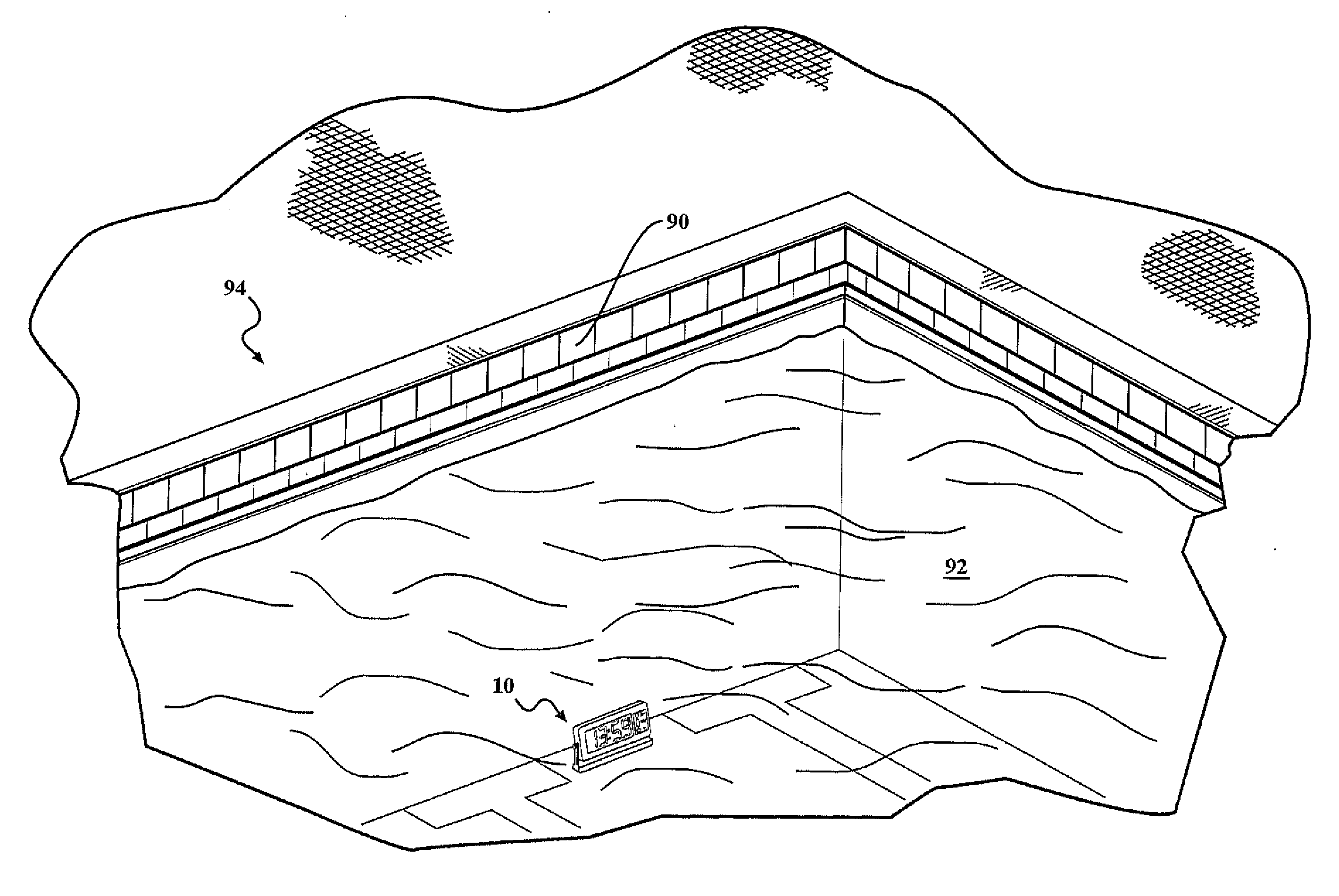
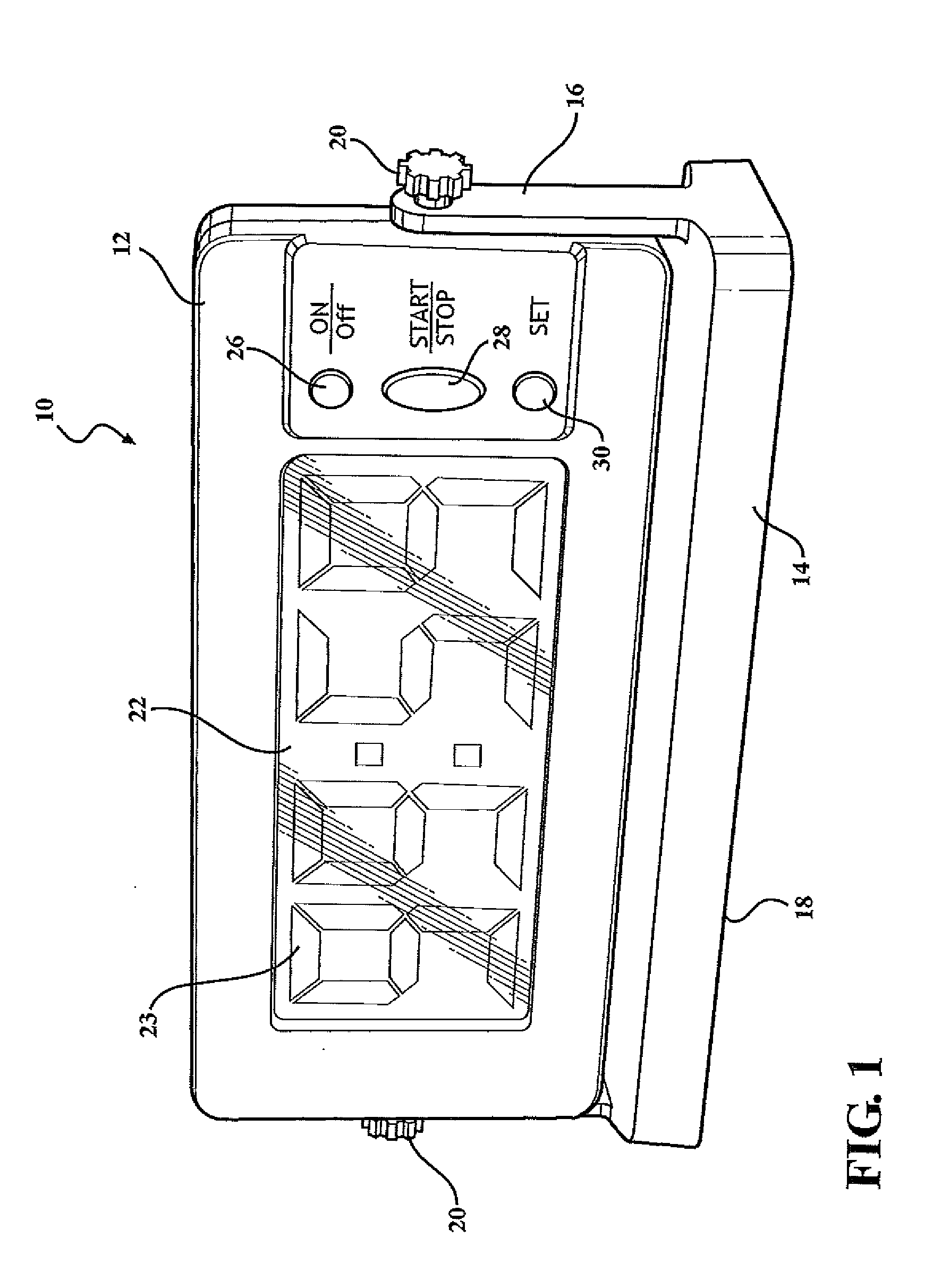
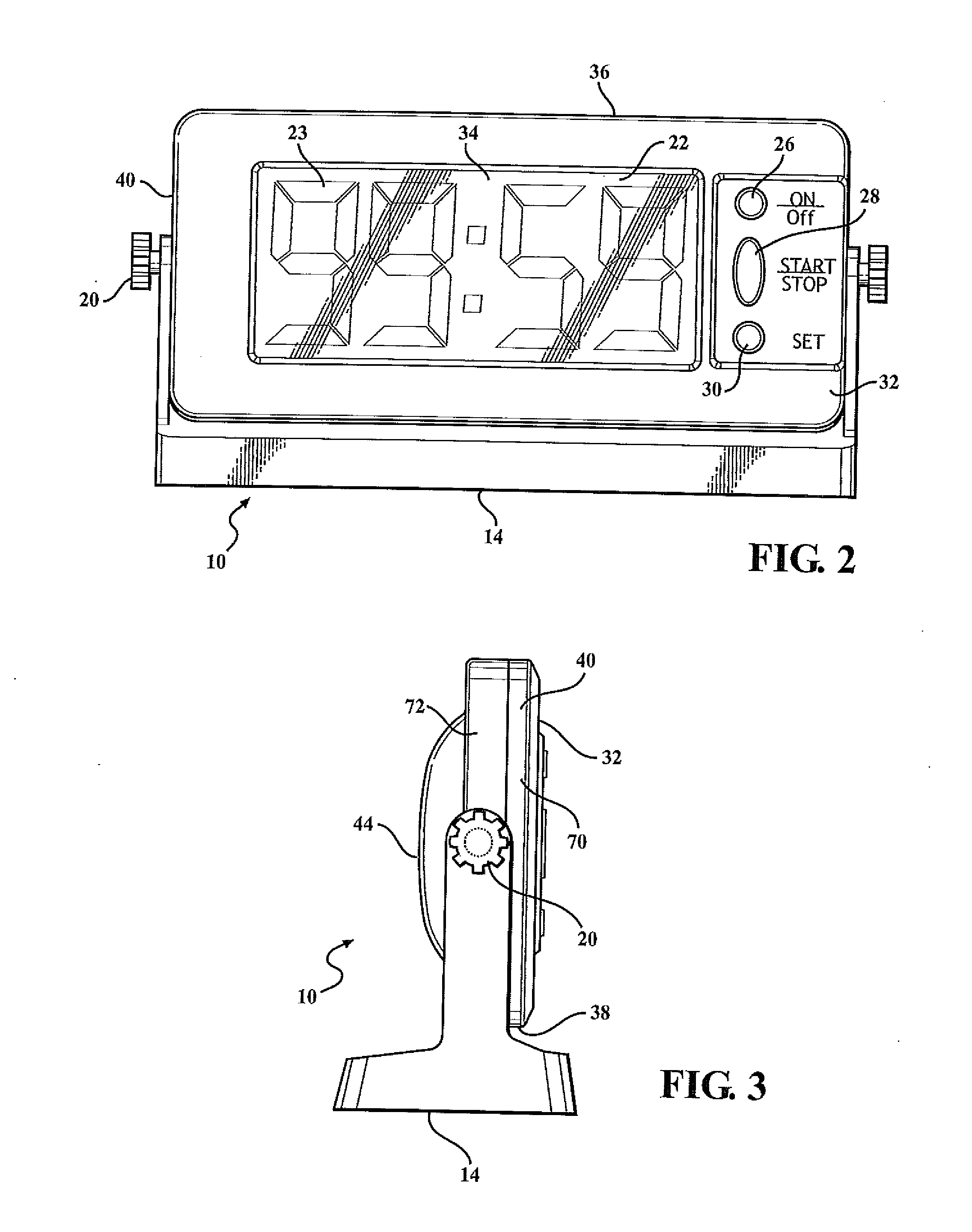
[0026]The following description will be best understood by reference to the drawings above described. The present invention is a timer 10 incorporating a case 12, a base 14 and a digital display 22. The digital display 22 is secured within the case 12, and the case 12 with its associated window 34 and operating controls 26, 28 and 30 are constructed as a watertight unit, so that the digital display 22 and its associated electronic circuitry are not damaged or rendered inoperative by exposure to water.

[0027]The basic configuration of the timer 10 as depicted in FIG. 1 and FIG. 8. The case 12 is pivotally secured to base 14 by a pair of brackets 16 which are provided with thumb screws 20 which engage threaded sockets (not shown) in the sides of the case 12. In this fashion, the case 12 may be rotated in relation to base 14 to vary the angle between the case 12 and the base 14, thereby allowing the user of the timer 10 to position the digital display 22 in relation to the surface on wh...


PUM


Abstract

The present invention is a submersible device for keeping track of a swimmer's session transpired times. It includes a case which is pivotally adjustable in relation to a base, and which contains both a watertight and a ballast compartment to decrease the buoyancy of the device when in use in water. The device may include a lap counter and a proximity sensor activated by the proximity of a swimmer wearing a proximity transmitter. A high contrast liquid crystal display is used to improve visibility.

Description

CROSS-REFERENCE TO RELATED APPLICATIONS[0001]This application is related to, and claims the benefit of priority from U.S. Provisional Patent Application Ser. No. 61 / 262,889, filed Nov. 19, 2009.FIELD OF THE INVENTION[0002]The present invention pertains to submersible timing and lap-counting devices for use by swimmers, and more particularly, to such devices utilizing high contrast displays with integral ballast systems.BACKGROUND[0003]For competitive swimmers, as well as for recreational lap swimmers, it is desirable to accurately time each lap, being one transit of the length of the pool and return. Each out and back lap typically occurs within the confines of a marked swimming lane, with the swimmer returning to the starting point in his or her lane at the beginning of each lap.[0004]Swimmers desire the ability to measure the elapse time for each lap. As a result of this need, a variety of timers and lap counters for swimmers have been developed.[0005]For example, U.S. Pat. No. 7,...

Claims


Application Information

Patent Timeline
Patent Type & Authority Applications(United States)
IPC IPC(8): G04B47/06G04F10/00
CPCG07C1/22G04G17/08
Inventor DAY, LAWRENCE JAMES
Owner PACE PAL
Why Eureka
Try Eureka