Screwdriver bit structure

a screwdriver and bit technology, applied in the direction of screwdrivers, wrenches, manufacturing tools, etc., can solve the problems of screwdriver bit failure, screwdriver bit failure, and end of screwdriver bit damage by torsion or cracking, so as to achieve stable operation and effectively reduce the consumption loss of screwdriver bit

Inactive Publication Date: 2011-11-24
ROTE MATE IND
View PDF13 Cites 34 Cited by
  • Summary
  • Abstract
  • Description
  • Claims
  • Application Information

AI Technical Summary

Benefits of technology

[0012]The connection section is designed as a polygonal cylinder that is mainly provided for combining a screwdriver bar or a pneumatic tool. A plurality of arc grooves is circularly disposed to a central axis of a front of the driving section to form an operating end for embedding with the locking member. The locking member is a screw with different types of embedding grooves. The front of the operating end is provided with an effective working section to incorporate the total length of the screwdriver bit. The characteristic of the invention is that a plurality of arc grooves is circularly disposed to a front of the driving section. A reinforcement section is preset between one end of each arc groove and a relative bottom edge of the driving section. An external diameter of a maximum cross-section is greater than a total length of the neck reducing section. A diameter of the neck reducing section is greater than or equal to a total length of the effective working section. In addition, an upper tapering transition

Problems solved by technology

When the locking member driven by the screwdriver bit is rotated to a tightening state by incorporating an electric tool with high rotational speed, the operating ends in fronts of the screwdriver bit may be damaged by torsion or cracked after reaching a yield point.
The forgoing conventional structures have defects.
After the torsion shearing stress carried by the screwdriver bit reaches a yield point, the screwdriver bit may be finally

Method used


Image

  • Screwdriver bit structure
  • Screwdriver bit structure
  • Screwdriver bit structure

Examples


Embodiment Construction

[0017]Other features and advantages of the present invention will become apparent from the following description of the invention which refers to the accompanying drawings.

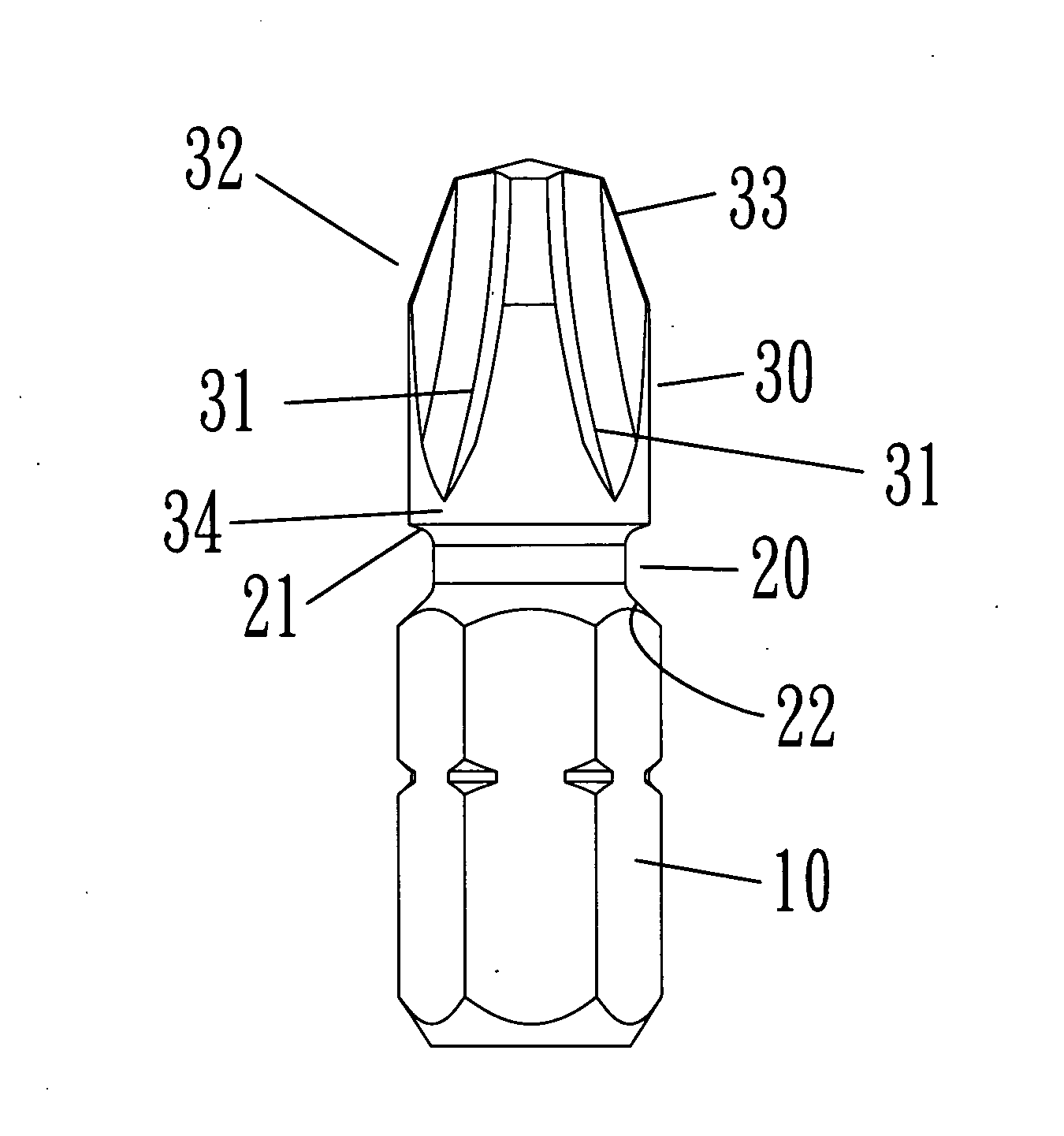
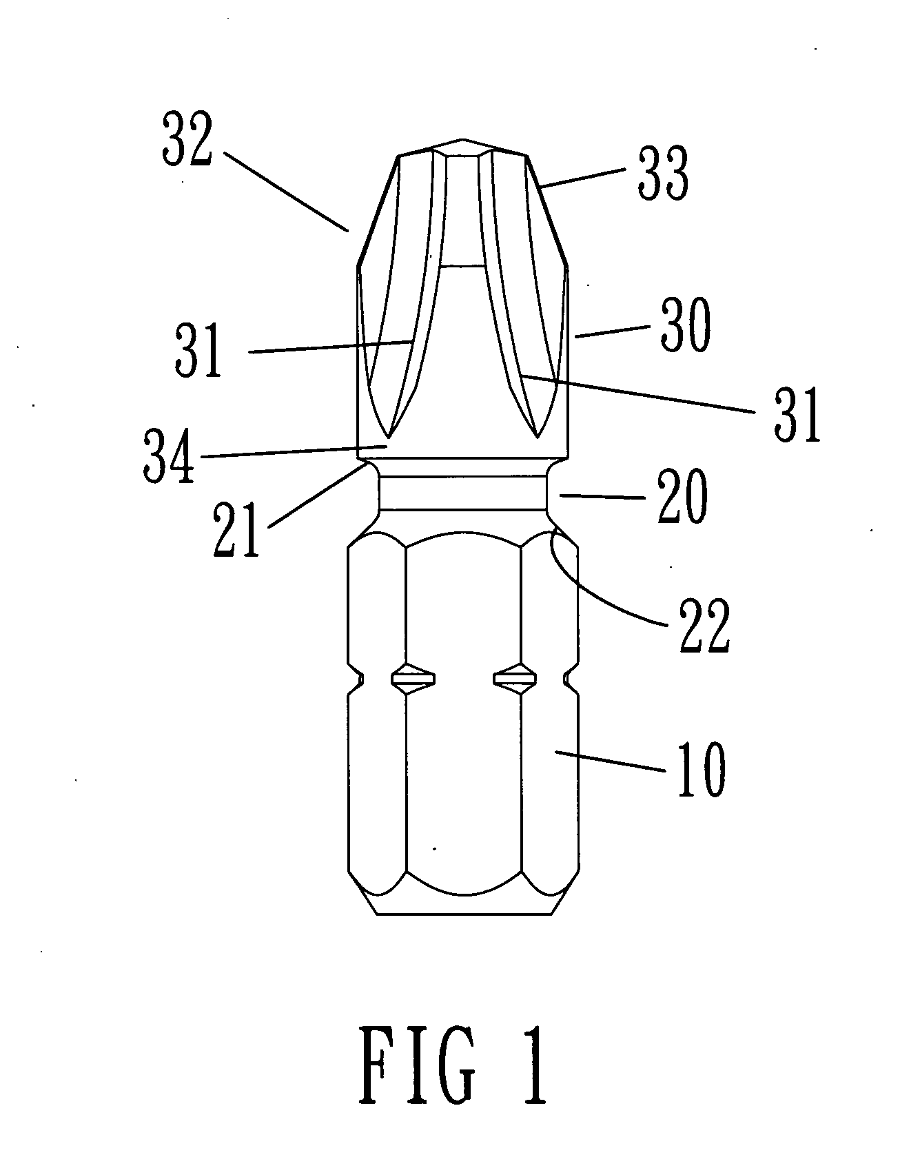
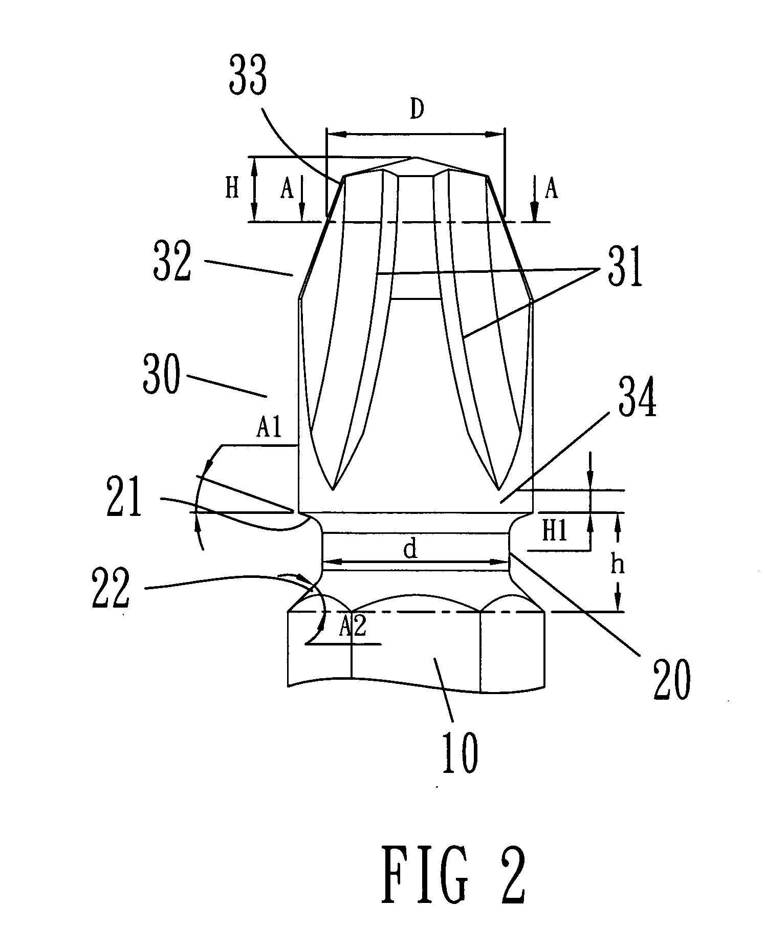
[0018]First, please refer to FIG. 1 to FIG. 3, a screwdriver bit structure is shown according to a preferred embodiment of the present invention. A screwdriver bit structure is a bar and composed of a connection section 10, a neck reducing section 20 and a driving section 30.

[0019]The connection section 10 is designed as a polygonal cylinder and mainly provided for combining a screwdriver bar (not shown in the figure) or a pneumatic tool (not shown in the figure).

[0020]The neck reducing section 20 is disposed between the connection section 10 and the driving section 30 and formed by the same bar.

[0021]A plurality of arc grooves 31 is circularly disposed to a central axis of a front of the driving section 30 and processed to form an operating end 32 capable of embedding with a locking member (not shown in the figur...


PUM


Abstract

A screwdriver bit structure sequentially comprises a connection section, a neck reducing section and a driving section. A plurality of arc grooves is circularly disposed to a front of the driving section to form an operating end capable of embedding with a locking member. An effective working section is disposed to a front of the operating end, the characterized in that a reinforcement section is preset between an end of each arc groove of the driving section and a relative bottom edge of the driving section. An external diameter of a maximum cross-section of the effective working section is greater than a length of the neck reducing section. An external diameter of the neck reducing section is greater than or equal to a length of the working section. An upper tapering transition is disposed between the neck reducing section and the driving section.

Description

FIELD OF THE INVENTION[0001]The present invention relates to a screwdriver bit structure, and more particularly to a screwdriver bit structure capable of improving structural strength and reducing the operation loss.BACKGROUND OF THE INVENTION[0002]In the industrial technology field, a locking member, such as screws, is frequently utilized for connection between articles. To deal with different sizes of the screw locking members and the screw locking members having different embedding grooves, replaceable screwdriver bits with different types and various sizes are developed to provide operators to perform the replacement in accordance with demands.[0003]A conventional screwdriver bit structure has a connection section and a driving section. The connection section is a polygonal cylinder that is fit to a screwdriver bar or an electric tool to perform the twist. The driving section is a post. A diameter of the driving section is smaller than an inner / tangency-diameter of the connectio...

Claims


Application Information

Patent Timeline
IPC IPC(8): B25B23/00
CPCB25B15/005B25B15/001
Inventor LAI, YING-TSUNG
Owner ROTE MATE IND
Why Eureka
Try Eureka