
Slitter with translating cutting devices

a cutting device and translation technology, applied in the field of finishing printed sheets, can solve the problems of not being able to produce more than 10 cut patterns without manual intervention, requiring more frequent changes to the finishing sequence, and not being able to meet consumer occupied environments, etc., to achieve the effect of simplifying operation and cleanup, reducing power consumption, and less audible nois

Inactive Publication Date: 2011-11-24
MIDWEST ATHLETICS & SPORTS ALLIANCE LLC
View PDF26 Cites 46 Cited by
  • Summary
  • Abstract
  • Description
  • Claims
  • Application Information

AI Technical Summary

Benefits of technology

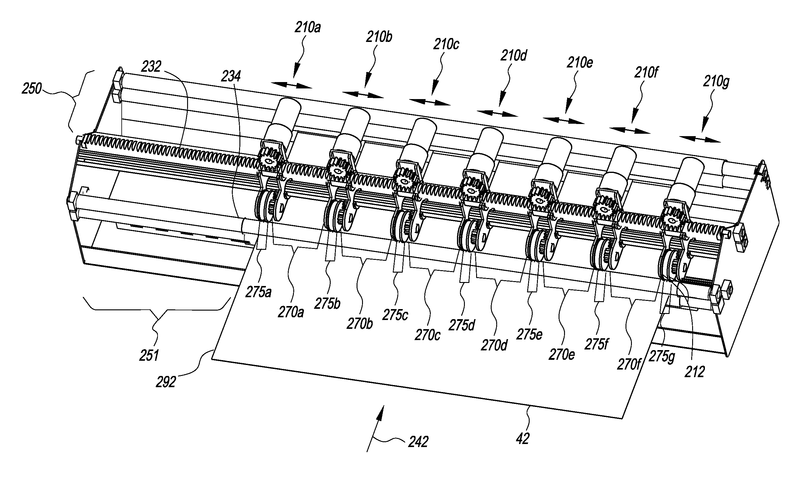
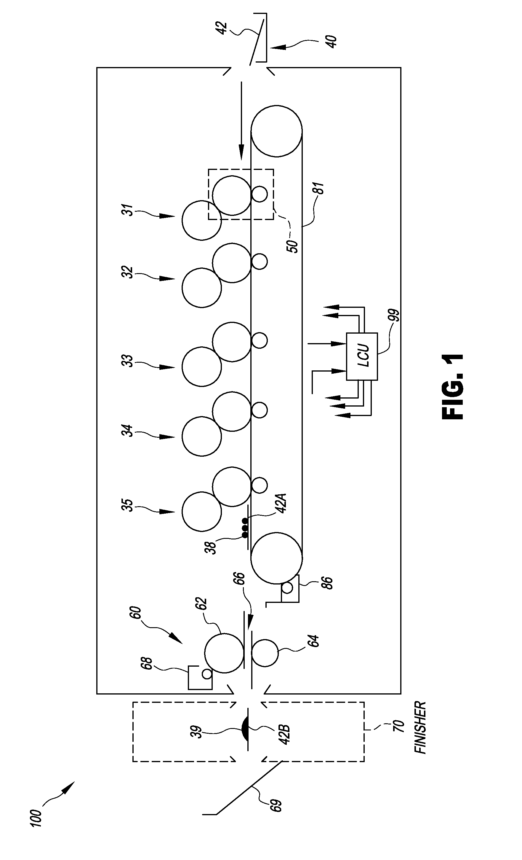
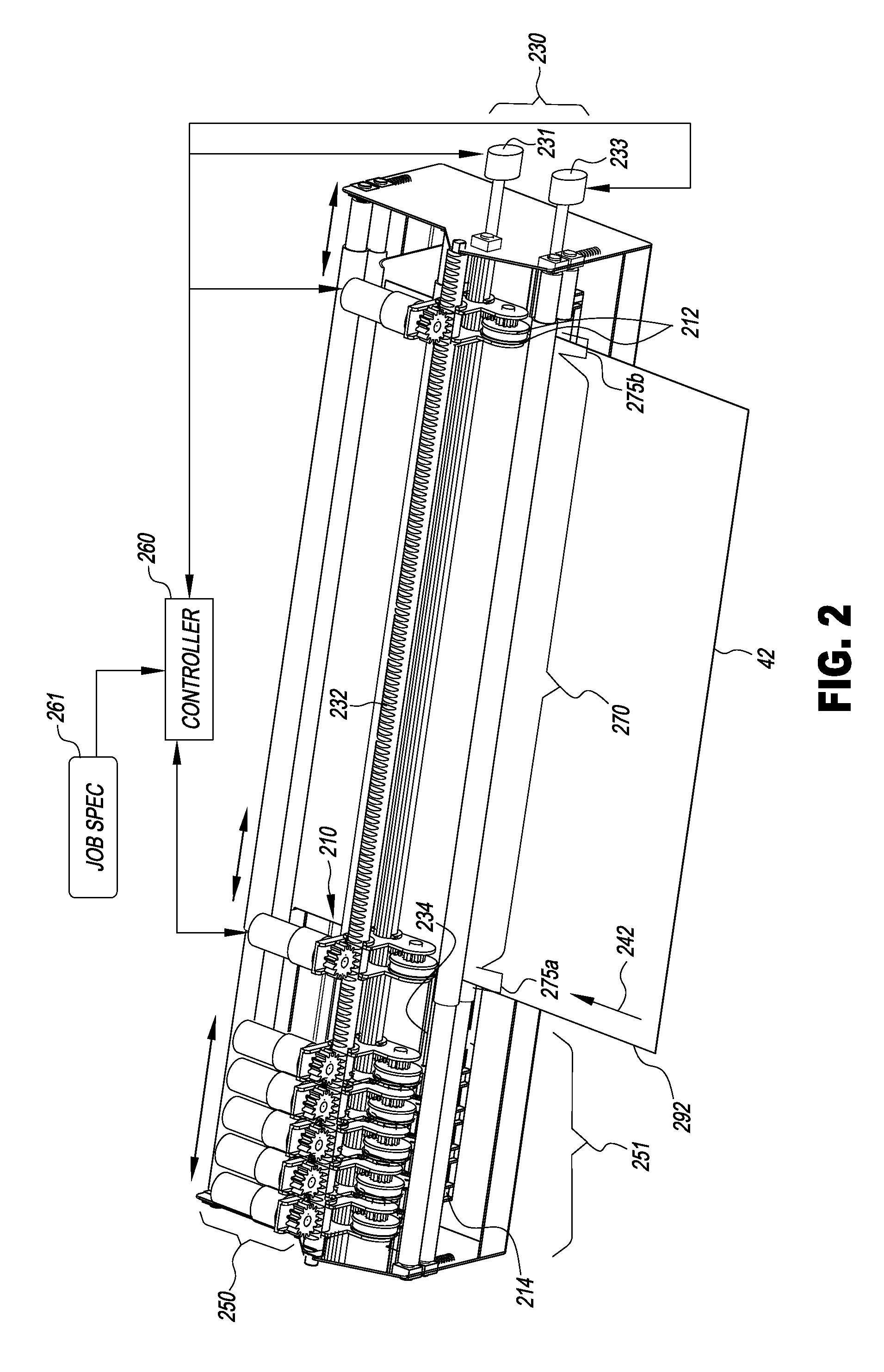
[0012]An advantage of this invention is that it uses small, light, inexpensive cutting machinery that can be used in environments without enough space for prior-art machines, or that require unskilled operators be able to use the machinery. The invention can emit less audible noise while operating due to its reduced power draw compared to guillotine cutters. It can finish each sheet of a print job individually without manual intervention. It can be employed with continuous-feed printing systems. It diverts the chad flow from the output flow, simplifying operation and cleanup.

Problems solved by technology

Conventional finishing equipment is typically not suited for use in consumer occupied environments such as stores or business establishments, and typically requires trained personnel to safely and effectively use it.
Furthermore, unlike offset presses which run a large number of copies of a single print job, digital printers can produce small numbers of copies of a job, requiring more frequent changes to the finishing sequence.
Moreover, the PL265 cutter can only store 10 cutting programs, so cannot produce more than 10 cut patterns without manual intervention.
However, the machine requires manual loading and unloading.
Furthermore, the CRICUT moves the sheet to be cut back and forth during cutting, making it unsuitable for high-volume applications that need continuous-speed sheet transport.
However, this apparatus trims the sides with fixed cutters not suitable for continuous-web operation.

Method used


Image

  • Slitter with translating cutting devices
  • Slitter with translating cutting devices
  • Slitter with translating cutting devices

Examples


Embodiment Construction

[0018]As used herein, the terms “parallel” and “perpendicular” have a tolerance of ±1°. In preferred embodiments, parallel and perpendicular structures have a tolerance of ±0.17° (±1 mm over 13″), or ±0.07° (±1 mm over 32″)

[0019]As used herein, “sheet” is a discrete piece of media, such as receiver media for an electrophotographic printer (described below). Sheets have a length and a width. Sheets are folded along fold axes, e.g. positioned in the center of the sheet in the length dimension, and extending the full width of the sheet. The folded sheet contains two “leaves,” each leaf being that portion of the sheet on one side of the fold axis. The two sides of each leaf are referred to as “pages.”“Face” refers to one side of the sheet, whether before or after folding. “Inboard” refers to closer to the center of a receiver; “outboard” refers to farther from the center of a receiver.

[0020]In the following description, some embodiments of the present invention will be described in term...


PUM

PropertyMeasurementUnit
circumferential speedaaaaaaaaaa
speedaaaaaaaaaa
areaaaaaaaaaaa

Abstract

Apparatus for cutting a moving receiver includes a plurality of cutting devices and a transport mechanism for selectively moving the cutting devices perpendicular to the feed direction of the receiver. Each cutting device includes two parallel cutting wheels and a pressure wheel arranged so that the cutting wheels are pressed laterally against the pressure wheel to form two cutting areas and a chad area arranged laterally between the cutting areas. A drive mechanism rotates the cutting wheels or pressure wheel of two or more of the cutting devices so that the rotating cutting wheels engage the moving receiver to cut the moving receiver parallel to its feed direction. A controller receives a job specification including two or more specified cut locations and causes the transport mechanism to laterally position two or more of the cutting devices to cut the moving receiver in the specified cut locations.

Description

FIELD OF THE INVENTION[0001]This invention pertains to the field of finishing printed sheets, and more particularly to such printed sheets produced using electrophotography.BACKGROUND OF THE INVENTION[0002]Customers of print jobs can require finishing steps for their jobs. These steps include, for example, folding printed or blank sheets, cutting sheets and trimming sheets to size and shape. For example, when producing business cards, the cards are printed on a large sheet of stiff card stock. After printing, individual cards are produced by cutting the sheets of cards into individual business cards.[0003]Conventional finishing equipment is typically not suited for use in consumer occupied environments such as stores or business establishments, and typically requires trained personnel to safely and effectively use it. Cutters typically include large guillotines that use heavy impacts to cut through thick stacks of paper. For example, the INTIMUS PL265 programmable cutter by MARTIN Y...

Claims


Application Information

Patent Timeline
Patent Type & Authority Applications(United States)
IPC IPC(8): B26D3/12B26D7/26B31B50/18
CPCB26D1/185B26D1/225B26D5/20B41J11/68B26D7/2635B31B2201/146B41J11/663B26D7/18B31B50/18Y10T83/659Y10T83/7826Y10T83/6588Y10T83/7876Y10T83/6651
Inventor KWARTA, BRIAN J.SHIFLEY, JAMES D.
Owner MIDWEST ATHLETICS & SPORTS ALLIANCE LLC
Learn More