Relative pump calibration for ultrafiltration control in a dialysis apparatus

a dialysis apparatus and relative pump technology, applied in the direction of positive displacement liquid engine, separation process, instruments, etc., can solve the problems of significant mechanical load on the cutoff valve that controls the switching, high noise, complex and costly, etc., and achieves simplified design, high-efficiency, and high-efficiency balancing devices.

Active Publication Date: 2016-06-02
GAMBRO LUNDIA AB
View PDF2 Cites 16 Cited by
  • Summary
  • Abstract
  • Description
  • Claims
  • Application Information

AI Technical Summary

Benefits of technology

[0020]The first aspect also involves a technique of generating a selected ultrafiltration rate in the dialyzer by establishing the main flow path and setting the frequencies of the pumps, based on the relation between the stroke volumes as determined in the relative calibration. In contrast to prior art techniques for controlling ultrafiltration, the first aspect makes it possible to directly and accurately control the difference in flow rates between the pumps during the treatment mode, by setting the frequency of the respective pump. This means that it is possible to dispense with highly advanced, complex and costly flow meters as well as noisy, complex and costly balancing devices. Thereby, the first aspect enables a simplification in the design of the dialysis apparatus. In the absence of balancing chambers and advanced flow meters, the robustness of the dialysis apparatus may also be increased. Further, the dialysis apparatus of the first aspect may be switched to the calibration mode at any time to re-calibrate the relation between the stroke volumes of the pumps. Thus, by the first aspect, the dialysis apparatus may compensate for changes or drifts in the stroke volumes of the pumps. In the absence of a balancing device, the dialysis apparatus may be designed to produce significantly less audible noise.

Problems solved by technology

For one, the switching of the balancing chambers may produce audible noise to the discomfort of the patient undergoing dialysis and also the caretakers.
Audible noise may be highly undesirable in a clinic setting as well as in a home setting.
Further, the cutoff valves that control the switching will be subjected to significant mechanical load over time and may start to leak dialysis fluid as result of wear and fatigue.
Any such leaks will produce errors in the resulting ultrafiltration.
Still further, errors in the dedicated filtration pump will have a significant impact on the accuracy of the ultrafiltration, and it may be necessary to take measures to carefully control and supervise the operation of the filtration pump.
Further, since the ultrafiltration is controlled based on the readings of one or more flow meters, ultrafiltration may be largely unaffected by leaks in the dialysis fluid supply system, as long as the flow meter(s) operate correctly.
However, flow meters with the required accuracy and precision may be quite costly and complex.
This means that it is possible to dispense with highly advanced, complex and costly flow meters as well as noisy, complex and costly balancing devices.

Method used


Image

  • Relative pump calibration for ultrafiltration control in a dialysis apparatus
  • Relative pump calibration for ultrafiltration control in a dialysis apparatus
  • Relative pump calibration for ultrafiltration control in a dialysis apparatus

Examples


Embodiment Construction

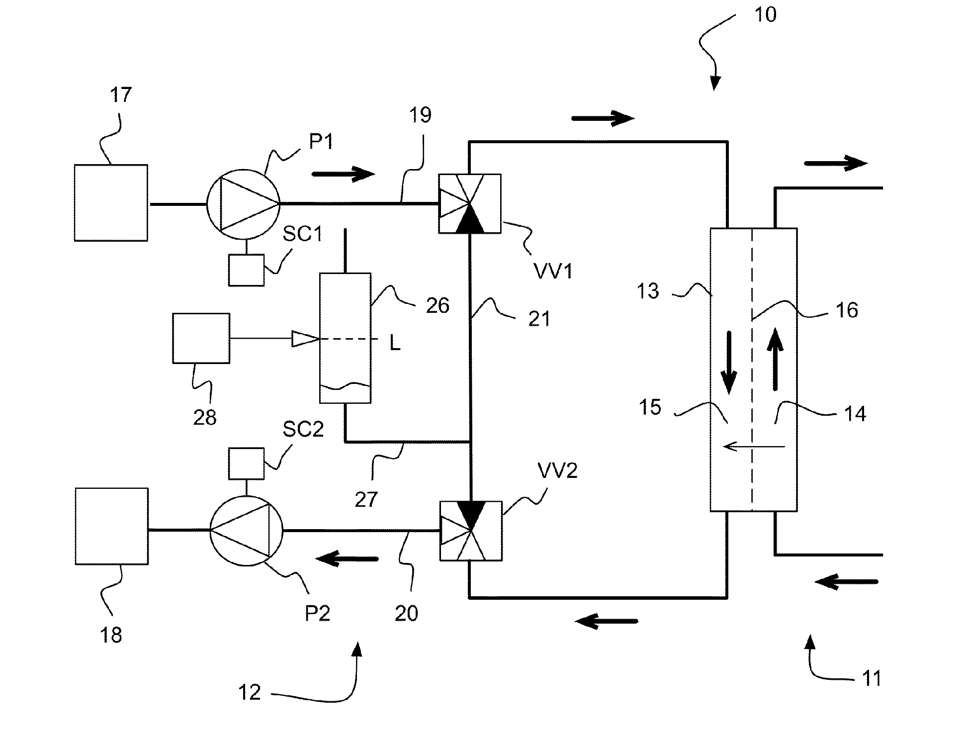
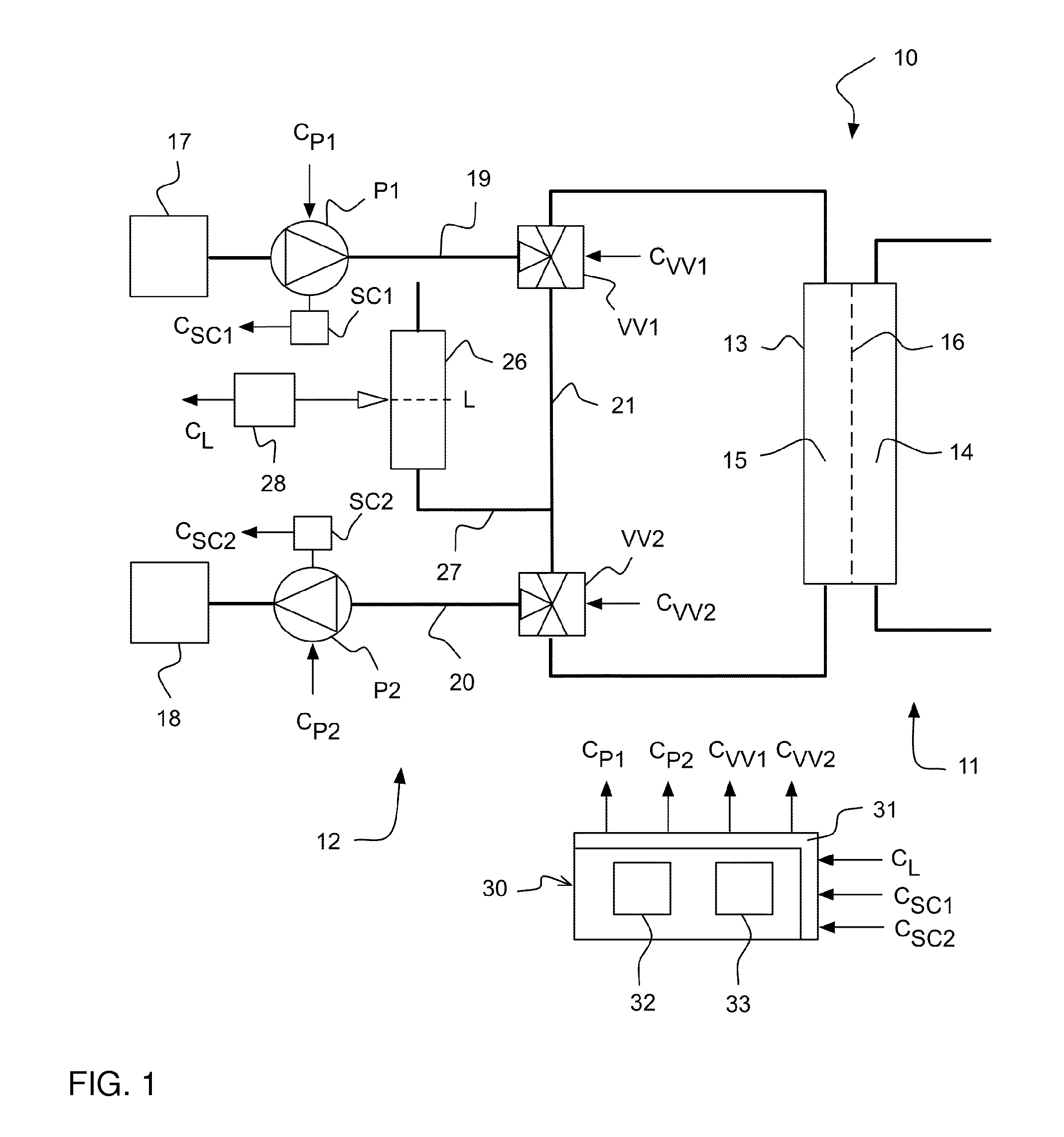
[0064]FIG. 1 illustrates an embodiment of a system 10 for ultrafiltration. The system 10 may be included in a dialysis apparatus. It is understood that only components relevant to the following description are represented in FIG. 1, with other components being well within the purview of one skilled in the art to ascertain. The system 10 comprises a blood circuit 11, a dialysis fluid circuit 12 and a dialyzer 13. The dialyzer 13 is a blood filtration unit that generally has a blood side 14 and a dialysis fluid side 15 separated by a semipermeable membrane 16. The blood circuit 11 is connected to an inlet and an outlet of the blood side 14. One or more pumps (not shown) are arranged in the blood circuit 11 to pump blood from a source (not shown) through the dialyzer 13 to a receptacle (not shown). The blood may e.g. be pumped from the cardiovascular system of a subject and back to the subject, as is well-known in the art. The dialyzer 13 may be any of the well-known dialyzers useful f...


PUM

PropertyMeasurementUnit
stroke volumeaaaaaaaaaa
frequencyaaaaaaaaaa
volumeaaaaaaaaaa

Abstract

A control unit (30) is arranged to control a dialysis fluid distribution system (12) comprising two volumetric pumps (P1, P2) and a dialyzer (13). The control unit (30) is operable in a calibration mode, to establish a bypass flow path that bypasses the dialyzer (13) and extends between the pumps (P1, P2) and to operate the pumps (P1, P2) at first and second calibration speeds so as to balance the flow rates generated by the pumps (P1, P2), e.g. based on a measured pressure or fluid level in dialysis fluid distribution system (12). The control unit (30) determines, based on the first and second calibration speeds, a relation between the stroke volumes of the pumps (P1, P2). The control unit (30) is further operable in a treatment mode, to establish a main flow path that extends between the first and second pumps (P1, P2) via the dialyzer (13) and to control the first and second pumps (P1, P2), based on the relation between their stroke volumes, to operate at a respective treatment frequency so as to generate a selected ultrafiltration rate in the dialyzer (13).

Description

TECHNICAL FIELD[0001]The present invention relates to a technique for controlling ultrafiltration in connection with dialysis, and in particular to a technique for calibrating one or more volumetric pumps for pumping a dialysis fluid through a dialyzer in a dialysis apparatus.BACKGROUND ART[0002]In treating chronic renal failure, various methods of purification and treatment of blood with machinery are used to replace the function of a healthy kidney. Such methods aim at withdrawing fluid and removing substances from the blood, and they may also involve adding fluid and substances to the blood. Such purification and treatment may be performed by pumping a dialysis fluid through a blood filtration unit, commonly denoted a dialyzer, in which fluid and substances are transported over a semi-permeable membrane. Diffusive mass transport through the membrane is predominant in hemodialysis (HD), whereas hemofiltration (HF) uses mainly convective mass transport through the membrane. Hemodia...

Claims


Application Information

Patent Timeline
Patent Type & Authority Applications(United States)
IPC IPC(8): A61M1/16G05B15/02
CPCA61M1/1601G05B15/02A61M1/1645A61M1/165A61M1/1647A61M1/16A61M1/34A61M2205/3334A61M2205/12A61M2205/70A61M2205/702A61M2205/52F04B13/00F04B23/06F04B49/065F04B51/00A61M1/3413A61M2205/15A61M2205/3331A61M2205/3389A61M1/3403A61M1/341
Inventor JANSSON, OLOFVARTIA, CHRISTIAN
Owner GAMBRO LUNDIA AB
Why Eureka
Try Eureka