Conductor of high voltage electrical apparatus
a high-voltage electrical and conductor technology, applied in the direction of conductors, open bus-bar installations, coupling device connections, etc., can solve the problems of increasing the weight of the apparatus, and achieve the effect of reducing cost and high reliability
- Summary
- Abstract
- Description
- Claims
- Application Information
AI Technical Summary
Benefits of technology
Problems solved by technology
Method used
Image

Examples
embodiment 1
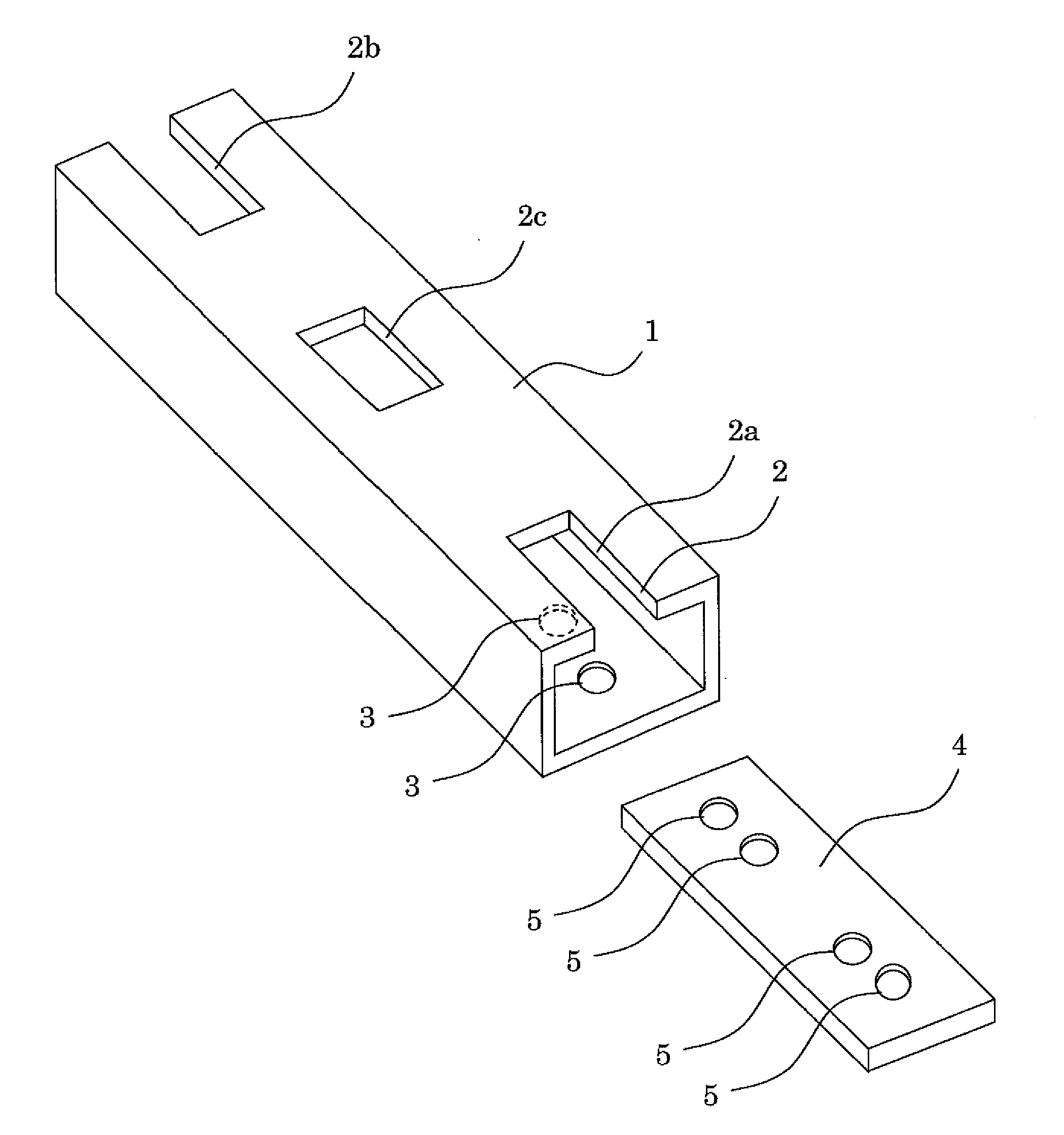
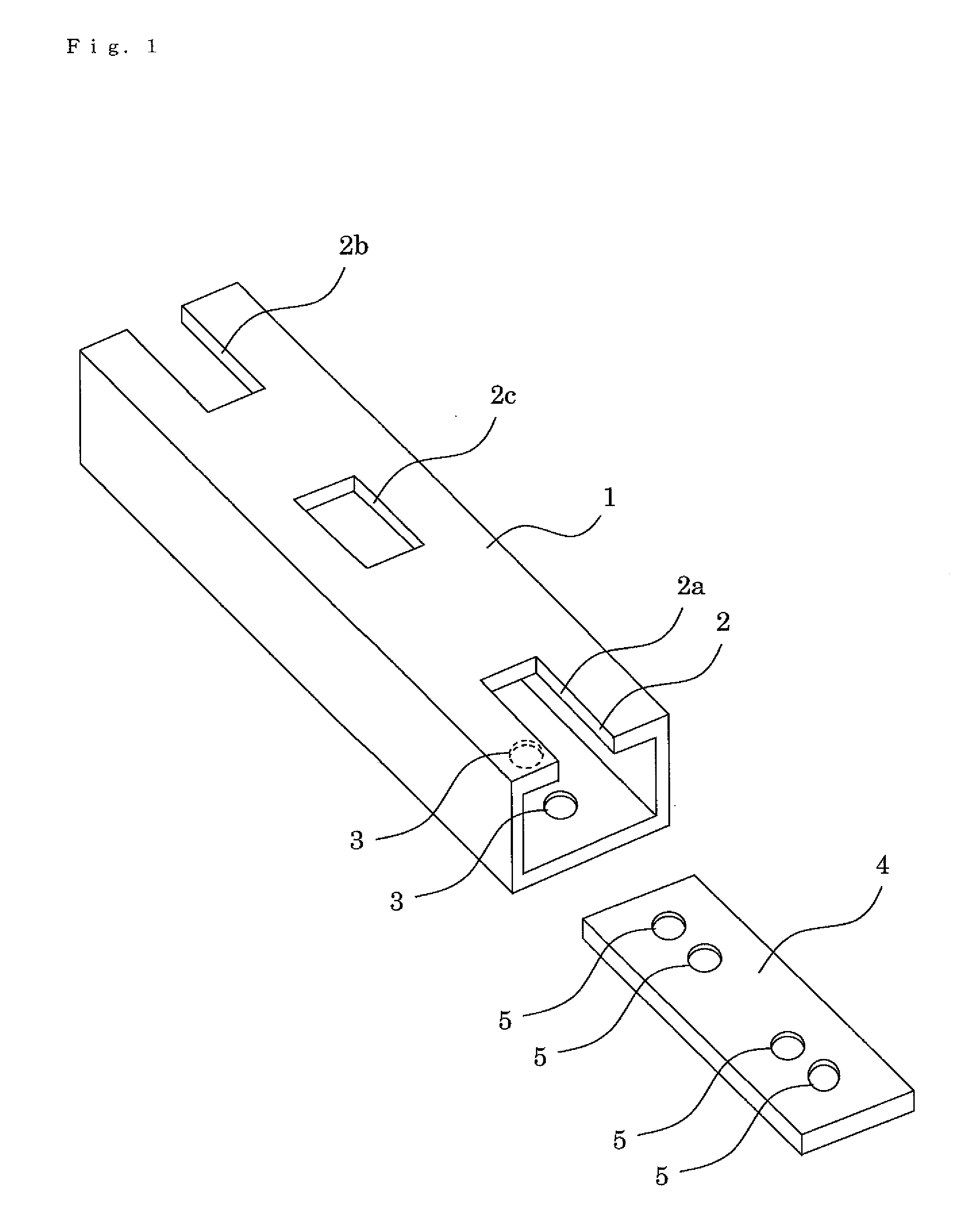
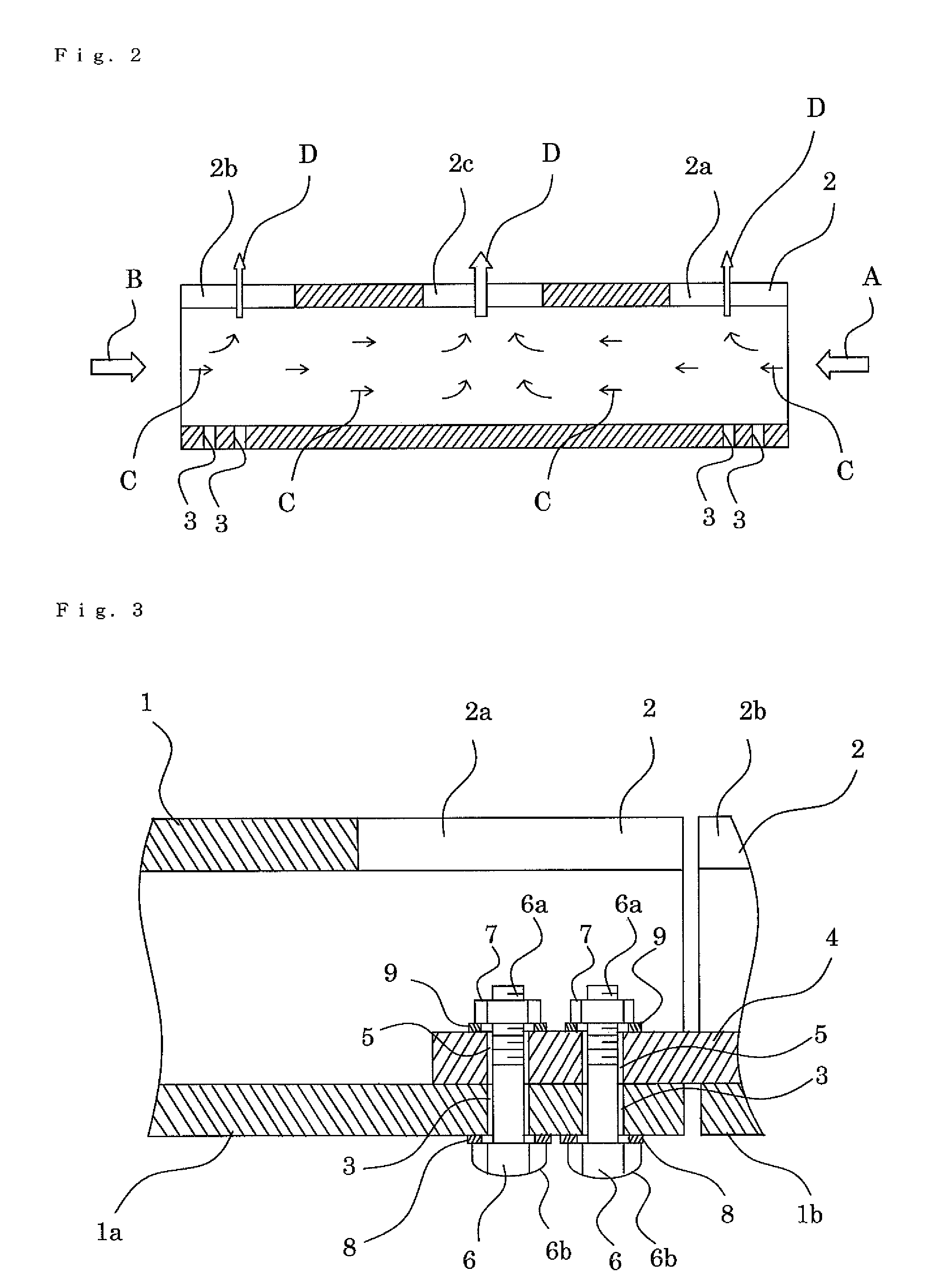
[0043]Hereinafter, Embodiment 1 of the present invention will be described with reference to FIG. 1 to FIG. 3. FIG. 1 is a perspective view showing a conductor of a high voltage electrical apparatus according to Embodiment 1 of the present invention. FIG. 2 is a sectional view showing the conductor of the high voltage electrical apparatus according to Embodiment 1 of the present invention. FIG. 3 is a relevant part sectional view showing the conductor of the high voltage electrical apparatus according to Embodiment 1 of the present invention.
[0044]In these respective drawings, reference numeral 1 denotes a polygonal tubular conductor formed from, for example, a square tube and is made of copper or aluminum. 2 denotes opening portions formed in at least one surface, for example, in an upper surface of the polygonal tubular conductor 1; and insulating gas such as SF6 gas, which flows in from both end portions of the polygonal tubular conductor 1 or from the directions of arrows A and ...
embodiment 2
[0054]Embodiment 2 of the present invention will be described with reference to FIG. 5 and FIG. 6. FIG. 5 is a perspective view showing a conductor of a high voltage electrical apparatus according to Embodiment 2 of the present invention. FIG. 6 is a relevant part sectional view showing the conductor of the high voltage electrical apparatus according to Embodiment 2 of the present invention.
[0055]In these respective drawings, reference numeral 1 denotes a polygonal tubular conductor; 1a denotes a first polygonal tubular conductor; 1b denotes a second polygonal tubular conductor; 3 denotes a through hole; 4 denotes a connection conductor; 5 denotes a through hole; 6 denotes a bolt; 6a denotes a threaded portion, 6b denotes a head portion; 7 denotes a nut; 8 denotes a washer; and 9 denotes a washer. 10 denotes an opening portion formed in at least one surface, for example, in an upper surface of the polygonal tubular conductor 1, the opening portion being brought into communication wi...
embodiment 3
[0065]Embodiment 3 of the present invention will be described with reference to FIG. 12. The description has been made on the case where the connection conductor 4 is placed on the inner surface of the lower surface side of the polygonal tubular conductor 1 in the aforementioned Embodiments 1 and 2; however, in FIG. 12, a connection conductor 4 is placed on the inner surface of the right side surface side of a polygonal tubular conductor 1 and the same effects as Embodiments 1 and 2 are exhibited. Incidentally, although not shown in the drawing, the opening portion 10 may be placed on the inner surface of the left side surface side of the polygonal tubular conductor 1, and the same effects are exhibited.
[0066]Furthermore, FIG. 13 shows an arrangement in which connection conductor 4 is dispersed at the inner surface of the left side surface side and the inner surface of the right side surface side of a polygonal tubular conductor 1; and FIG. 14 shows an arrangement in which connectio...
PUM
 Abstract
Description
Claims
Application Information
 - R&D
- Intellectual Property
- Life Sciences
- Materials
- Tech Scout
- Unparalleled Data Quality
- Higher Quality Content
- 60% Fewer Hallucinations
Browse by: Latest US Patents, China's latest patents, Technical Efficacy Thesaurus, Application Domain, Technology Topic, Popular Technical Reports.
© 2025 PatSnap. All rights reserved.Legal|Privacy policy|Modern Slavery Act Transparency Statement|Sitemap|About US| Contact US: help@patsnap.com